Spherical Billboard of a Line Strip with Geometry Shader

Hi everyone! This is my first time posting here. I made a similar thread at gamedev.net, but unfortunately I got no response, so I will try my luck here instead! My problem is very similar to this topic from 10 years ago (since I’m new here I can’t post full links, so I will just give the topic info): Billboard geometry shader posted by Vexator with topic id 6561

However, the solution posted there redirects me to the khronos forums home page.

I will briefly describe the problem also posted at gamedev. Since I can’t post links, you can google search the thread by typing : Spherical Billboard of a Line Strip with Geometry Shader in OpenGL

I’m interested in rendering hair in real time using OpenGL, so I studied Nvidia’s presentation from SIGGRAPH 2010. In it, they suggest rendering each line segment as camera facing quad instead of the GL_LINE_STRIP primitive.

My camera is built following the tutorial found at the learnopengl page.

The camera class is:

class Camera{
public:
   // camera Attributes
   glm::vec3 Position;
   glm::vec3 Front;
   glm::vec3 Up;
   glm::vec3 Right;
   glm::vec3 WorldUp;
   // euler Angles
   float Yaw;
   float Pitch;
   // camera options
   float MovementSpeed;
   float MouseSensitivity;
   float Zoom;
   
   // ... (camera functions) ...
}

For the “eye vector”, I use the Front vector of the camera class. The line coordinates are passed in a VBO. Here is the Veretx Shader:

#version 430

layout (location = 0) in vec3 aPos;
layout (location = 1) in vec3 aColor;
layout (location = 2) in float aTransparency;
layout (location = 3) in float aSegmentIndex;
layout (location = 4) in float aThickness;

uniform vec3 camera_position;


uniform mat4 model;
uniform mat4 view;

out vec3 color;
out float transparency;

out VS_OUT{

float thickness;
vec3 eye_vector;
vec4 point;

}vs_out;

void main()
{
   gl_Position =  view* model * vec4(aPos, 1.0);

color = aColor;

vs_out.eye_vector = normalize(camera_position - gl_Position.xyz);

vs_out.thickness = aThickness;
vs_out.point = gl_Position;

transparency = aTransparency;
}

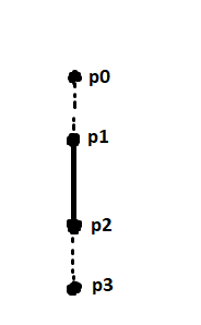
Each line has two points and each point has its own struct called vsout. In it, I store the normalized distance from the camera to the point (eye vector), and the thickness value. Each vertex is multiplied by the model_view matrix (view * model). The Geometry Shader is as follows:

#version 430

layout (lines) in;
layout (triangle_strip, max_vertices = 4) out;

uniform mat4 projection;

in VS_OUT{

float thickness;
vec3 eye_vector;
vec4 point;

}gs_in[];


void main(){

float radius = gs_in[0].thickness / 2;

vec4 p1 =  gs_in[0].point;
vec4 p2 =  gs_in[1].point;

vec3 tangent = normalize(p1.xyz - p2.xyz);

vec3 expand_direction1 = normalize(cross(gs_in[0].eye_vector,tangent));
vec3 expand_direction2 = normalize(cross(gs_in[1].eye_vector,tangent));

vec3 Pos;

Pos = p1.xyz + expand_direction1 * radius;
gl_Position = projection * vec4(Pos, 1.0);
EmitVertex();

Pos = p1.xyz - expand_direction1 * radius;
gl_Position =  projection * vec4(Pos, 1.0);
EmitVertex();

Pos = p2.xyz + expand_direction2 * radius;
gl_Position =  projection * vec4(Pos, 1.0);
EmitVertex();

Pos = p2.xyz - expand_direction2 * radius;
gl_Position = projection * vec4(Pos, 1.0);
EmitVertex();

EndPrimitive();
}

First I compute the tangent as suggested in the paper by Nvidia. Then, I compute the cross product of the eye vector and the tangent for each point of the line. This cross product is the expand direction. Then, I compute the ammount of expansion for each point and multiply the result with the projection matrix (I use perspective projection).

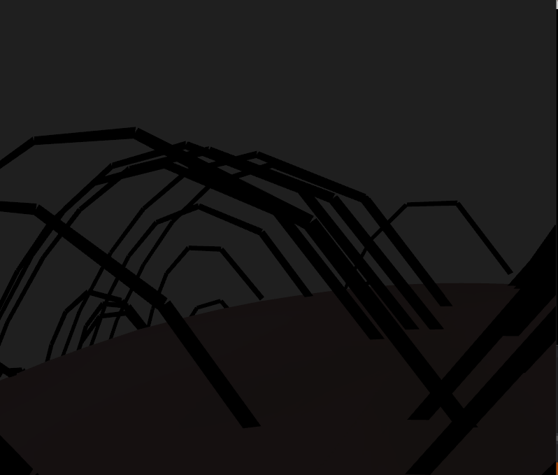
Even though it looks good from a distance, there are some issues when I zoom in. There seem to be some discontinuities in each line segment, as if each segments rotates differently. All quads should face the camera, and the bottom of one quad should align with the top of the next (if that makes sense ).

You can see the pictures at the gamedev forum because it will still not let me upload an image.

I’ve tried many different things but nothing seems to work out for me. This is the closest I’ve been to a correct bilboard geometry shader, but the disconnecting lines and the weird rotation when the camera zooms in kinda ruins the whole implementation. Thank you for reading!

Ok, here’s that forum thread you wanted to link to:

Finding a working link to the solution posted there took a few minutes, but I found it. Here you go:

The Internet Archive:

Current link on the Khronos Forums:

Ah yes the Internet Archive didn’t even cross my mind! Thank you taking time to find the old thread. I will try the technique and will post an update soon.

Sorry for the long wait but other things happened in the meantime…

So I checked the solution provided, but it doesn’t work, because this is a different problem. In classical billboarding, the geometry shader takes one vertex and expands it in 4 directions in x and y axis.

In this problem, the geometry shader takes 2 vertices as input (a line) and expands the top and bottom vertex, so that they are connected in a triangle strip. The tangent must follow the camera movement.

Here is the pseudocode from the Nvidia presentation:

Float3 Tangent = normalize(vertex[1].Position – vertex[0].Position);
Float3 sideVec = normalize(cross(eyeVec, tangent));
float4x3 pos;
float3 width0 = sideVec * 0.5 * width * vertex[0].width;
float3 width1 = sideVec * 0.5 * width * vertex[1].width;
pos[0] = vertex[0].Position - width0;
pos[1] = vertex[0].Position + width0;
pos[2] = vertex[1].Position - width1;
pos[3] = vertex[1].Position + width1;

The code assumes that there is one eye vector. Shouldn’t there be two vectors? One from the camera “front” vector to the top vertex, and another one from the camera “front” vector to the bottom vertex?

It doesn’t matter. If eyeVec is the vector from the viewpoint to some point on the line, sideVec will be perpendicular to the plane containing the the line and the viewpoint. Given that sideVec is normalised, its value will be the same regardless of which point on the line is used to generate eyeVec.

Oh ok I understand. Another question for the eye vector distance would be : do I use the camera’s position in the 3D world (as it is passed in the vertex shader), or the camera’s front vector that points towards the scene? The front vector seems to almost work, but there are still disconnected lines and weird rotations of the quad segment when I rotate the camera in close distance.

As a note, the vertex/geometry shaders haven’t changed from the original post.

Why do you want that? If you’re rendering billboarded cylinders (or conical frusta, i.e. tapering cylinders), the object/world/clip-space dimensions are determined by the radius of the cylinder and are independent of the distance to the viewpoint.

If you’re trying to render thick lines, you’d need to scale by eye-space -Z (and you’d want the quads to be perpendicular to the eye-space Z axis, not tilted to face the viewpoint).

1 Like

Hmmm could you please explain the last sentence because I’m afraid I didn’t quite understand that. The eye vector will be the -z axis of which parameter?

If you’re drawing thick lines (rather than cylinders), you’d use the eye-space -Z axis is the eye vector, not the vector between a point on the line and the viewpoint.

1 Like

Oh ok, so its going to be

vec3 eye_vec = vec3(0.0, 0.0 ,-camera.position)

I’m sorry if I still don’t grasp something, but I’m still a bit beginner/almost intermediate :stuck_out_tongue:

vec3(0,0,-1) will suffice. The resulting sideVec is normalised so magnitudes don’t matter.

It seems the problem is still there for some reason. Is it because the vertices are in model-view space? And the projection is done in the geometry shader when the final vertex is emmited? I also did the the projection-view-model transform only in the vertex shader but the results were worse. I’m definitely missing something here because this problem has tormented me for months :joy:

The calculations can be done in object space, world space or eye space. But all vectors involved need to be in the same space. So if the vertex positions are in eye space the eye position is (0,0,0) and the eye vector is just the position of one of the vertices.

If you’re drawing line strips, you will get gaps at the joins if the vertex shader processes individual segments; to avoid that, the input primitive type needs to be lines_adjacency, and the side vector at each vertex needs to be the average of the side vectors for the line segments which share that vertex. And you’ll need to add an extra vertex at the beginning and end of the strip so the first and last segments have an adjacent vertex.

Ok, so I did a bit of research about the line strip adjacency and I modified the code so that it draws GL_LINE_STRIP_ADJACENCY instead of the simple GL_LINE_STRIP.
Basically I duplicated the top and bottom vertex to create the adjacency.

The geometry shader now takes 4 vertices, 2 adjacent and 2 that describe the line (as seen in the next sketch):
adjacency2
p0 and p3 are the adjacent vertices. You said “the side vector at each vertex”, but shouldn’t it be the side vector at each segment since we are taking the cross product of the eye vector with the tangent?

The modified geometry shader is as follows:

layout (lines_adjacency) in;
layout (triangle_strip, max_vertices = 4) out;

...


void main(){

	// The adjacent vertices
	vec4 p0 = gs_in[0].point;
	vec4 p3 = gs_in[3].point;

	float radius = gs_in[1].thickness / 2;

	vec4 p1 =  gs_in[1].point;
	vec4 p2 =  gs_in[2].point;

	vec3 tangent1 = normalize(p0.xyz - p1.xyz);
	vec3 tangent2 = normalize(p1.xyz - p2.xyz);
	vec3 tangent3 = normalize(p2.xyz - p3.xyz);
	
	
	vec3 eye_vec = vec3(0,0,-1);
	vec3 side_vector1 = normalize(cross(eye_vec,tangent1));
	vec3 side_vector2 = normalize(cross(eye_vec,tangent2));
	vec3 side_vector3 = normalize(cross(eye_vec,tangent3));
	
	vec3 side_vector = (side_vector1 + side_vector2 + side_vector3) / 3;

	vec3 Pos;

	Pos = p1.xyz + (side_vector * radius);
	gl_Position = projection * vec4(Pos, 1.0);
	EmitVertex();

	Pos = p1.xyz - (side_vector * radius);
	gl_Position =  projection * vec4(Pos, 1.0);
	EmitVertex();

	Pos = p2.xyz + (side_vector * radius);
	gl_Position =  projection * vec4(Pos, 1.0);
	EmitVertex();

	Pos = p2.xyz - (side_vector * radius);
	gl_Position = projection * vec4(Pos, 1.0);
	EmitVertex();

	EndPrimitive();
	
}

Unfortunatey there are still gaps at the joins in the line.

You have 3 side vectors from the 3 segments. The side vector added to p1 should be the average of those from p0-p1 and p1-p2. The side vector added to p2 should be the average of those from p1-p2 and p2-p3.

	vec3 side_vector012 = (side_vector1 + side_vector2) / 2;
	vec3 side_vector123 = (side_vector2 + side_vector3) / 2;

	vec3 Pos;

	Pos = p1.xyz + (side_vector012 * radius);
	gl_Position = projection * vec4(Pos, 1.0);
	EmitVertex();

	Pos = p1.xyz - (side_vector012 * radius);
	gl_Position =  projection * vec4(Pos, 1.0);
	EmitVertex();

	Pos = p2.xyz + (side_vector123 * radius);
	gl_Position =  projection * vec4(Pos, 1.0);
	EmitVertex();

	Pos = p2.xyz - (side_vector123 * radius);
	gl_Position = projection * vec4(Pos, 1.0);
	EmitVertex();
1 Like

Oh wow! It worked! I will definitely read the solution again to try and understand it in depth. Thank you so much! I can finally move on to the next task now!

After a bit of research, the reason why there are gaps at the line’s joints is because OpenGL does not support line miter. Luckily enough for my hair project, a cubic bezier tessellation is going to mitigate the problem, since more vertices are introduced, giving a more “rounded” line. So even the one cross product in the geometry shader should be enough, since the problem will be hidden with tessellation.

GClements’s solution works well and is quite elegant for line segments where there is no line tessellation involved.