Proper color interpolation

So basically, I am trying to plot a 2D color map of an equispaced grid. Each coordinate (x, y) is associated with a color and I draw every quad using two triangles. My hope was that OpenGL’s color interpolation would smooth every corner’s color and produce a nice and smooth-looking gradient over the whole map.

However, the result is not what I expected and not that good looking:

image

Any idea how I could improve this ? I can provide more code details and whatnot if needed :slight_smile:

Reminds me of:

See the last link above for GLSL code showing how to do this in OpenGL.

I think there was a thread here on this on this a few years back. Ah! Here it is:

Also, snapping a triangle grid over this helps to make a little more sense of what you’re seeing.

triangle_blending3

Thanks for the answer - I’ve taken a quick look to the resources you linked and to be honest I kinda hoped there’d be a simpler solution, being quite very new to OpenGL and this stuff in general.

I’ll include my code here for those that’d be interested to take a look at what I did to get this result: code here

Using bilinear interpolation would certainly improve the result. The easiest way to do this is to store the data as a 2D texture and and use GL_LINEAR filtering. If you try to do it with vertex attributes, you have the issue that each triangle needs the values from all four vertices of the quad, including the vertex which isn’t part of the triangle.

Bilinear interpolation will eliminate the “crease” along the main diagonal, but will probably still result in visible banding. If you want smooth contours, you need to use bicubic interpolation. That requires the use of 16 values (a 4x4 grid of vertices forming a 3x3 grid of quads centred on the one being rendered). The calculation is essentially:

T interp_cubic(float u, T c[4])
{
    T k3 =  c[3] - 3*c[2] + 3*c[1] -   c[0];
    T k2 = -c[3] + 4*c[2] - 5*c[1] + 2*c[0];
    T k1 =           c[2]          -   c[0];
    T k0 =                  2*c[1]         ;
    return (u * (u * (u * k3 + k2) + k1) + k0) / 2;
}

T interp_bicubic(float u, float v, T c[4][4])
{
    T x[4];
    for (int i = 0; i < 4; i++)
        x[i] = interp_cubic(u, c[i]),
    return interp_cubic(v, x);
}

where T is the type being interpolated, typically either a float or vector.

This can be optimised somewhat by pre-calculating coefficients from the sample values.

Apoligizes for some dumb newbie questions - but where/how exactly am I supposed to perform this cubic interpolation ? I am not using textures at the moment (see code) and am not exactly sure how I should use them in my case. I’m trying to take a look at some tutorials about textures, but I still fail to see how it is supposed to help my case (even though I know there must be something interesting somewhere in there…)

Here is a video I made about rendering quads in opengl

OK, so I’ve somehow managed to implement the stuff you referred here. However, it yields the following result:

image

As I understand from the paper, it is required to discard some elements to avoid undesired behaviour when some lines intersect (?). I must have done something wrong, but not quite sure what exactly…

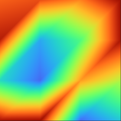
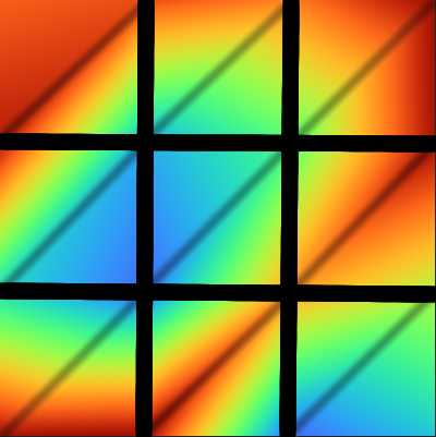
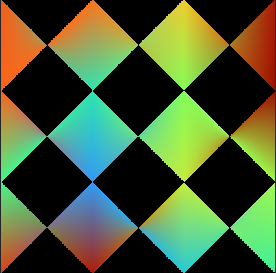
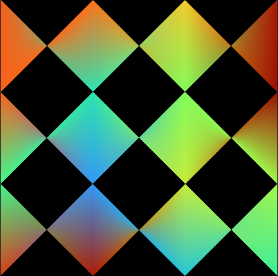
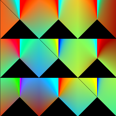
Try this. These are the shaders from the video I made above

Vertex

uniform mat4 mvp;
uniform int vid_offset = 0;
uniform vec3 pos_offset;

out VS_OUT
{
    vec4 color;
	vec2 texCoord;
} vs_out;

void main(void)
{
    vec4 vertices[] = vec4[](vec4(-0.5, -0.5, 0.0, 1.0),
                             vec4( 0.5, -0.5, 0.0, 1.0),
                             vec4( 0.5,  0.5, 0.0, 1.0),
                             vec4(-0.5,  0.5, 0.0, 1.0));

    vec2 texcoords[] = vec2[](vec2(0.0, 0.0),
                              vec2(1.0, 0.0),
                              vec2(1.0, 1.0),
                              vec2(0.0, 1.0));

    vec4 colors[] = vec4[](vec4(1.0, 0.0, 0.0, 1.0),
                           vec4(0.0, 1.0, 0.0, 1.0),
                           vec4(0.0, 0.0, 0.0, 1.0),
                           vec4(1.0, 1.0, 1.0, 1.0));

	vertices[0].xyz += pos_offset;

    gl_Position = mvp * vertices[(gl_VertexID + vid_offset) % 4];
    vs_out.color = colors[(gl_VertexID + vid_offset) % 4];
	vs_out.texCoord = texcoords[(gl_VertexID + vid_offset) % 4];
}

Geometry

#version 450 core

layout (lines_adjacency) in;
layout (triangle_strip, max_vertices = 4) out;

in VS_OUT
{
	vec4 color;
	vec2 texCoord;
} gs_in[4];

out GS_OUT
{
	noperspective vec2 v[4];
	noperspective float area[4];
	flat float oneOverW[4];
	flat float depth[4];		// optional for quad depth emulation

	flat vec4 color[4];			// our regular vertex attribs
	flat vec2 texCoord[4];
} gs_out;

double area(dvec2 a, dvec2 b)
{
	return a.x*b.y - a.y*b.x;
}

void main(void)
{
	int i, j, j_next;

	vec2 v[4];

	for (i=0; i<4; i++) {
		float oneOverW		= 1.0 / gl_in[i].gl_Position.w;
		v[i]				= gl_in[i].gl_Position.xy * oneOverW;
		gs_out.oneOverW[i]	= oneOverW;
		gs_out.depth[i]		= (((gl_in[i].gl_Position.z * oneOverW) + 1.0) / 2.0) * oneOverW;
		gs_out.color[i]		= gs_in[i].color * oneOverW;
		gs_out.texCoord[i]	= gs_in[i].texCoord * oneOverW;
	}

	for (i=0; i<4; i++) {
		// Mapping of polygon vertex order to triangle strip vertex order.
		//
		// Quad (lines adjacency)    Triangle strip
		// vertex order:             vertex order:
		// 
		//        1----2                 1----3
		//        |    |      ===>       | \  |
		//        |    |                 |  \ |
		//        0----3                 0----2
		//
		int reorder[4] = int[]( 0, 1, 3, 2 );
		int ii = reorder[i];
		dvec2 vector[4];

		for (j=0; j<4; j++) {
			vector[j] = dvec2(v[j]) - dvec2(v[ii]);
			gs_out.v[j] = vec2(vector[j]);
		}
		for (j=0; j<4; j++) {
			j_next = (j+1) % 4;
			gs_out.area[j] = float(area(vector[j], vector[j_next]));	// if we use float for area it's possible to run out of precision
		}

		gl_Position = gl_in[ii].gl_Position;

		EmitVertex();
	}
}

Fragment

#version 450 core

uniform sampler2D tex1;
uniform bool texturesEnabled;

in GS_OUT
{
	noperspective vec2 v[4];
	noperspective float area[4];
	flat float oneOverW[4];
	flat float depth[4];			// optional for quad depth emulation

	flat vec4 color[4];				// our regular vertex attribs
	flat vec2 texCoord[4];
} fs_in;

// interpolated variables
vec4 fsColor;
vec2 fsTexCoord;

// out
out vec4 color;

void QuadInterpolation()
{
	uint i, i_next, i_prev;

	vec2 s[4];
	float A[4];

	for (i=0; i<4; i++) {
		s[i] = fs_in.v[i];
		A[i] = fs_in.area[i];
	}

	float D[4];
	float r[4];

	for (i=0; i<4; i++) {
		i_next = (i+1)%4;
		D[i] = dot(s[i], s[i_next]);
		r[i] = length(s[i]);
		if (fs_in.oneOverW[i] < 0) {  // is w[i] negative?
			r[i] = -r[i];
		}
	}

	float t[4];

	for (i=0; i<4; i++) {
		i_next = (i+1)%4;
		if(A[i]==0.0) {
			t[i] = 0;									// check for zero area + div by zero
		}
		else {
			t[i] = (r[i]*r[i_next] - D[i]) / A[i];
		}
	}

	float uSum = 0;
	float u[4];

	for (i=0; i<4; i++) {
		i_prev = (i-1)%4;
		u[i] = (t[i_prev] + t[i]) / r[i];
		uSum += u[i];
	}


	float lambda[4];

	for (i=0; i<4; i++) {
		lambda[i] = u[i] / uSum;
	}

	/* Discard fragments when all the weights are neither all negative nor all positive. */

	int lambdaSignCount = 0;

	for (i=0; i<4; i++) {
		if (fs_in.oneOverW[i] < 0) {

			if (lambda[i] > 0) {
				lambdaSignCount--;
			} else {
				lambdaSignCount++;
			}

		}
		else {
			if (lambda[i] < 0) {
				lambdaSignCount--;
			} else {
				lambdaSignCount++;
			}
		}

	}
	if (lambdaSignCount != 4) {
		if(!gl_HelperInvocation) {	// we need this for mipmap calculation with textures otherwise edge pixels fail
			discard;
		}
	}

	float interp_oneOverW = 0.0;
	float depth = 0.0;

	fsColor	= vec4(0.0);
	fsTexCoord = vec2(0.0);

	for (i=0; i<4; i++) {
		interp_oneOverW		+= lambda[i] * fs_in.oneOverW[i];
		depth				+= lambda[i] * fs_in.depth[i];
		fsColor				+= lambda[i] * fs_in.color[i];
		fsTexCoord			+= lambda[i] * fs_in.texCoord[i];
	}

	fsColor		/= interp_oneOverW;
	fsTexCoord	/= interp_oneOverW;
	depth		/= interp_oneOverW;

	// write depth value
	gl_FragDepth = depth;
}

void main(void)
{
	QuadInterpolation();

	if(texturesEnabled) {
		color = texture(tex1,fsTexCoord);
	}
	else {
		color = fsColor;
	}
}

You want to use glDrawArrays with GL_LINE_ADJACENCY

Consider why you’re having this problem. By interpolating colors, you’re asking the GPU to compute blended colors across a triangle with absolutely no knowledge of the color of the 4th vertex in the “quad”.

If you (as GClements suggests) instead:

  • store your color data in a 2D texture (instead of in a vertex attribute),
  • interpolate a 2D texture coordinate (s,t) across your triangles to do the texture lookup (instead of a color),
  • do the lookups using LINEAR filtering (this is bilinear filtering)

You’re going to get:

  • reasonable 2D texture coordinates within your quad, and
  • you’re going to make use of dedicated hardware on the GPU that will blend across neighboring texel colors (in X and Y) to give you smooth color blending across the entire quad (**), which is what you want.

** If your texture color data is no higher res than the vertex data. It could be higher or lower.

Moreover, by using a texture, you can get other filtering benefits such as higher-quality minification filtering (with MIPmaps), higher-quality edge-on filtering (with anisotropic filtering), etc. That may or may not be important to you.

Right. Which is the jist/tradeoff of the technique in that GLSL sample code and paper PDF I pointed to, SnaKyEyeS.

On the one hand, you get quad-based perspective-correct interpolation across a “quad”, even though you’re really rendering triangles.

On the other hand, you end up having to pass around 4X the vertex attribute data so that something on the GPU can re-implement quad-based perspective-correct interpolation on top of the tri-based perspective-correct interpolation that the GPU natively supports (essentially bypassing that capability). In the case of the GLSL example code, it’s the geometry shader and fragment shader that have to deal with this.

Just updated the code with your shaders; still the same results… :frowning:
(I am using vertex color; not textures, if it’s relevant in any way)

image

I tried to implement this, as you suggested (as you can see, the results are not that great, still have some bugs to find out I guess).

I will definitely have a look at using textures if the interpolation you first mentioned ends up not working !

Ok. It’s going to give you a similar bilinear filtered result though (assuming you implement/apply both techniques correctly), if your data is planar.

So before you do, it might first help if you describe exactly what is wrong with the result you’re getting, in your view. That is what is the difference between your current result and the result you want?

Is it that you need higher-order filtering as GClements suggested, that filters/blends across a larger area than just one quad?

Is your data really associated with the cells and not the points (i.e. connection-dependent data, not node-dependent data)? From the result it sounds like you’re seeking, I suspect not.

1/ the first picture I sent at the beginning of the conversation; as discussed, the color interpolation looks “bad” because of the triangulation process (which is indeed logical).

2/ in the second picutres I sent later, the interpolations looks good (much better), but I have those discarded fragments that spoil the result.

What I essentially want to do is something akin to the imshow function of matplotlib - check the first example. To be exact, I am simulating the Cahn-Hilliard equation and wish to live-plot the solution evolution at each iteration of my numerical solver. Thus, I have a 2D array (128x128 nodes) of values which can easily be converted to color values using any given colormap. I already have a somewhat acceptable result using a simple triangulation process, but being the perfectionnist I am I would like to clear out the remaining interpolation “un-niceness”…

The result on the whole 128x128 grid looks like this (at a given timestep):

Your result looks correct. As for discarded fragments, it’s not fragment it’s whole polys.
How are you passing the data? You can’t just switch to line adjacency and expect it to work. Each poly must have 4 unique vertices.

Also check if you have backface culling enabled.

I did change the way I passed data. I have my NxN array of vertices and a 4(N-1)² array of elements used for ordering (I have to draw (N-1)² quads) - as you recommended, I use glDrawElements(GL_LINES_ADJACENCY, 4*(N-1)*(N-1), GL_UNSIGNED_INT, 0);. The rest is done as in your code.

Vertex definition (colors are in a separate buffer):

    GLfloat positions[2*N*N];
    for (int i = 0; i < N; i++) {
        for (int j = 0; j < N; j++) {
            int ind = i*N+j;
            positions[2*ind  ] = (float)(-1.0 + 2.0*i/(N-1));
            positions[2*ind+1] = (float)(-1.0 + 2.0*j/(N-1));
        }
    }

and element ordering buffer:

    GLuint elements[4*(N-1)*(N-1)];
    for (int i = 0; i < N-1; i++) {
        for (int j = 0; j < N-1; j++) {
            int ind  = i*N+j;
            int ind_ = i*(N-1)+j;

            elements[4*ind_  ] = ind;
            elements[4*ind_+1] = ind+1;
            elements[4*ind_+2] = ind+N;
            elements[4*ind_+3] = ind+N+1;
        }
    }

I did not have backface culling enabled - enabling it increases (logically so) the amount of culled polys.

You can try removing the discard statement from the fragment shader but i don’t think that’s the issue.

Indeed it is not, I already tried that. It yields an ever weirder result:
image

I think you must be mixing the vertices up somehow. Try just drawing a single quad. I should mention vertices need to have all the same winding, otherwise you can end up with a twisted quad.

Indeed you were right, I made a little mistake…
However, there’s still those little “border” effects between quads - it’s better but I guess if I want to have a better result, I have to use textures as Dark_Photon mentionned :slight_smile:
Thanks a lot for your help :smiley:

image

This topic was automatically closed 183 days after the last reply. New replies are no longer allowed.