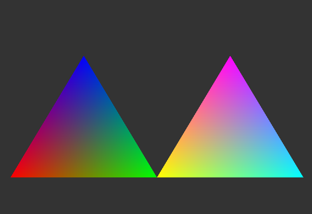
Below are two simple triangles I draw using default fragment interpolation.
The problem is the right triangle seems brighter than the left. It seems right from mathematical point of view, as color of three 3 vertices of the left are 100, 010, 001, i.e. RGB. While the color of the right are 110, 011, 101. So when interpolate, the right should be brighter.
But then I think it, from the color point of view (i.e. physical real color), the left triangle is just RGB, while the right is yellow, purple and … (I don’ know its name). And each color, e.g. the yellow should be comparable to the color red or green or blue, i.e, the color yellow in the right is as bright as blue or green or red (in physical world). The same will be applied for the other two vertices of the right.
So from color point of view, i.e. if each color is physical color, the right triangle is just a rotated version of the left, i.e, yellow is between red and green, purple is just between red and blue and so on. So, from the color point of view, the right triangle should be as bright as the left. Or the maths and the color are conflicted?