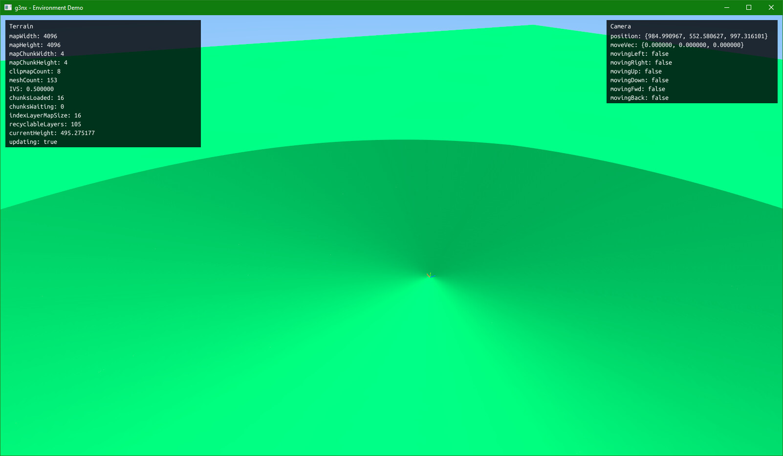
Apologies if this is a wall of text. I would post more images to illustrate my issue but I am a new user so can only embed one in my post. I am unsure exactly where the problem is so I’m trying to be as comprehensive as I can. I am working on a terrain clipmap implementation with chunk streaming using texture arrays, and I’m seeing weird behaviour along one axis where chunks border each other:
To give a bit of context to what’s going on, when the game starts I create a bunch of geometries which follow the camera around, always updating so the individual vertices are locked to fixed steps. Each layer out gets less fine, and so we always end up showing nice detailed terrain around the camera and lower res stuff far away. Because the vertices are constantly moving, I’m setting the Y axis value and texture coordinates for the normal maps in the vertex shader rather than updating vertex attributes on the CPU and piping them through every time.
I used texelFetch when sampling my heightmap, which works because the vertices in the finest clipmap layer always have a 1:1 ratio with pixels, so there is no need for any blending/interpolation. A subset of
heightmaps are loaded into TEXTURE_2D_ARRAY at any one time, and removed/added when they go in and out of range. To reduce memory footprint the array is sized only to the amount of chunks that will be in range at any one time, and layers are recycled.
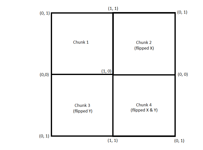
I’ve used the same method to add normal mapping for terrain lighting, except I’m sampling it in the fragment shader now based on UV coordinates output by the VS. Initially I had a problem where I had intended to tile all my normal maps in the same orientation for simplicity, but this presented a problem where a vertex which occupied a chunk boundary had to have one or both of the UV coordinates set to 0 or 1 depending on which face was being rendered, and that wasn’t going to work. So I decided on using a coordinate system in blocks of 4 chunks where chunks in odd (0-based) rows or columns go backwards to avoid any “jump” in texture coordinates.
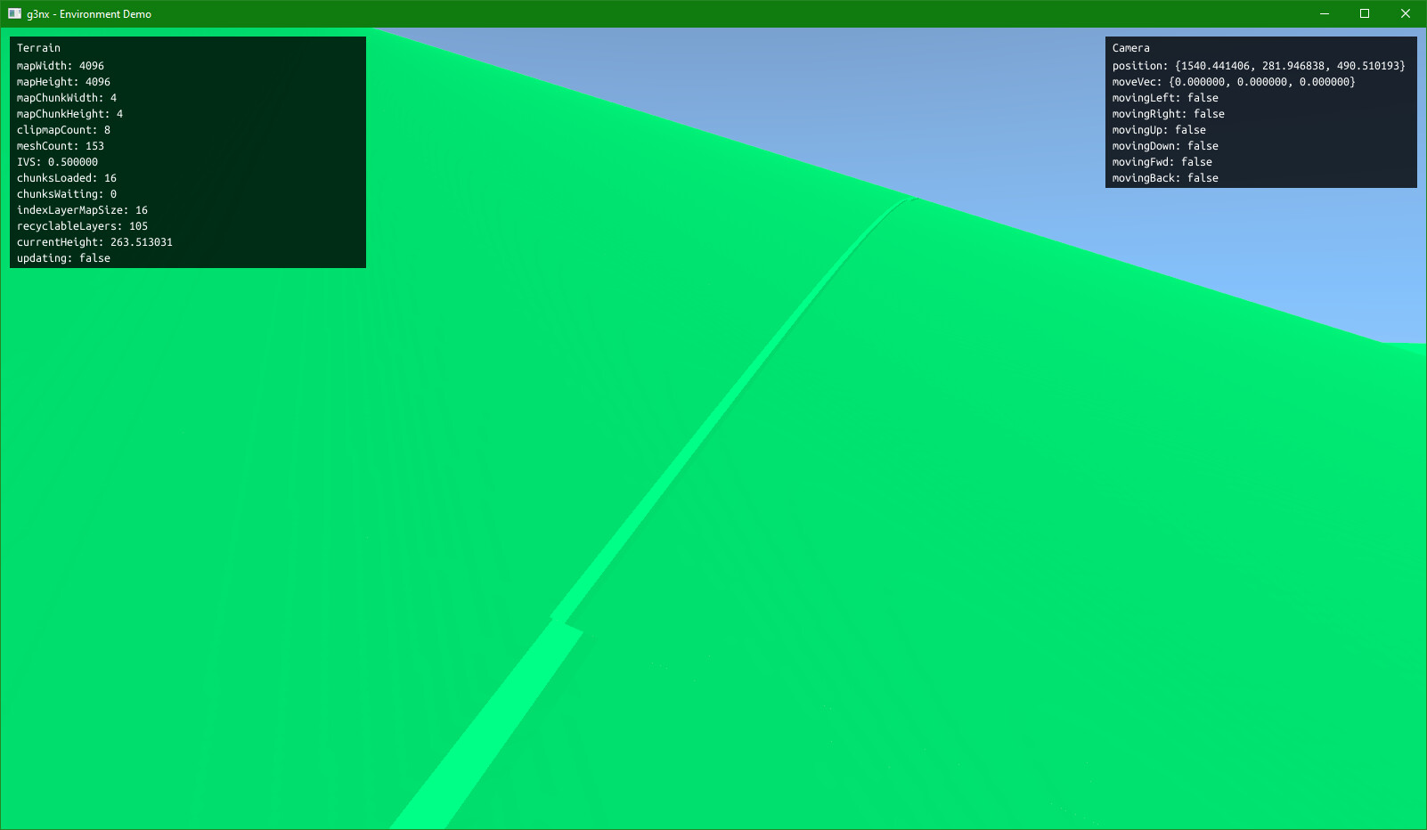
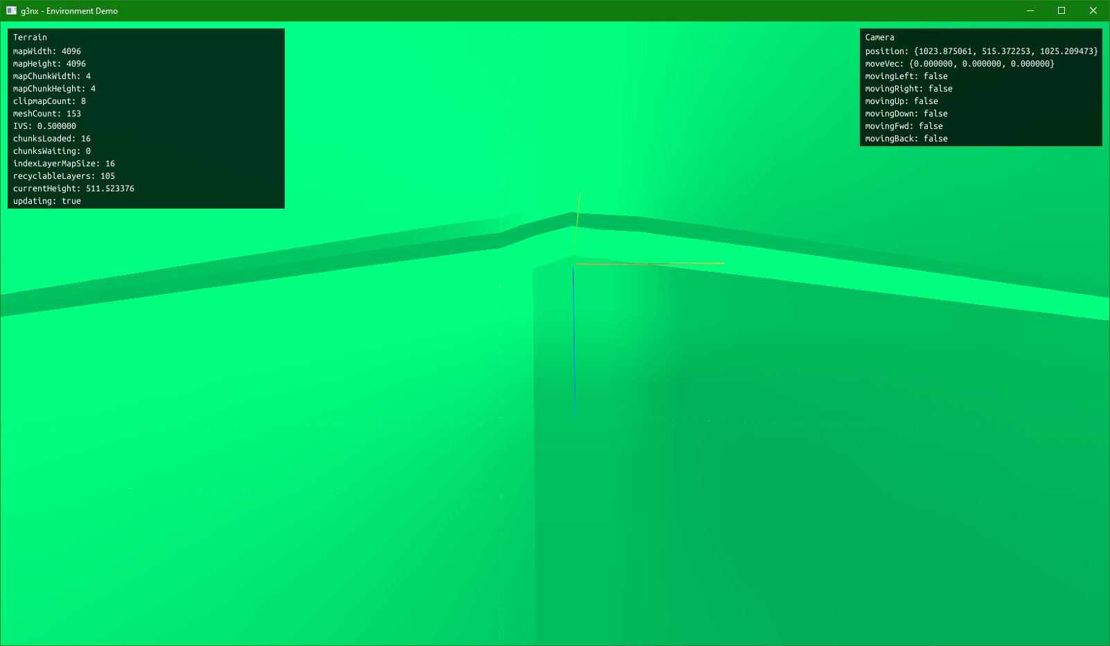
After reworking the normal map generator to accommodate for this, and regenerating myself some correctly oriented normal maps, the issue seemingly disappeared but only for the X boundary between chunks. It hasn’t solved the issue for the other side. The artefact seems to occupy only the last row in any chunk, but no longer the last column.
Colouring the vertices based on their texture coordinates shows no issues. It all interpolates smoothly (final colour = (s, t, 0.0)).
I’ve run through the shader code numerous times with a calculator and paper and I’m pretty sure the numbers should work, but I just cannot figure out what this weird line is. I’m posting shader code in case someone spots a basic error in my shader code I’ve missed. IVS is the intra-vertex spacing, and for this should be treated as 0.5 always. Chunks are 1024x1024 pixels, taking up 512x512u at IVS = 0.5. The math to get the normal map UV is a triangle wave in the range [0-1] with an offset for t. Texture wrap mode is set to CLAMP_TO_EDGE, and the normal maps are generated as one large image before being chopped up and flipped, so I know that when reoriented in the shader they should still be seamless.
Vertex Shader
//Vertex shader for terrain.
#include <attributes>

uniform mat4 ModelViewMatrix;
uniform mat3 NormalMatrix;
uniform mat4 MVP;

uniform float Scale;
uniform vec2 Offset;
uniform mat4 RotMatrix;
uniform float IVS;
uniform float MinHeight;
uniform float MaxHeight;
uniform int ChunkSize;
uniform int MapWidth;
uniform int MapHeight;
uniform sampler2DArray Heightfield;
uniform sampler2D LayerIndexMap;

out float Height;
out vec3 NormalMapCoords;

void main() {
    // Get the XZ world coordinates of the vertex.
    vec2 vertXZ = Offset + (RotMatrix * vec4(VertexPosition, 1.0)).xz * Scale;
    float chunkWorldSize = ChunkSize * IVS;

    // Get the chunk xy and the layer index to sample from.
    int chunkX = int(floor(vertXZ.x / chunkWorldSize));
    int chunkY = int(floor(vertXZ.y / chunkWorldSize));
    float layerIdx = texelFetch(LayerIndexMap, ivec2(chunkX, chunkY), 0).r * 256.0;

    // Scale the vertex coords to the chunk image size to get pixel XY coordinates to sample height from.
    vec2 pixelXY = vec2(
        mod(vertXZ.x, chunkWorldSize) / IVS,
        mod(vertXZ.y, chunkWorldSize) / IVS
    ); // if IVS = 0.5 and vertXZ = 511.5, then pixelXY = 1023
    float sampledHeight = texelFetch(Heightfield, ivec3(pixelXY.x, pixelXY.y, layerIdx), 0).r;

    // Multiply by 0 if we're out of range.
    sampledHeight = sampledHeight * int(chunkX >= 0 && chunkX < MapWidth && chunkY >= 0 && chunkY < MapHeight);

    // Scale sampled value by the height range.
    Height = ((MaxHeight - MinHeight) * sampledHeight) + MinHeight;
    vec3 finalPos = vec3(VertexPosition.x, Height, VertexPosition.z);

    // Set the vertex position.
    gl_Position = MVP * mat4(1.0) * vec4(finalPos, 1.0);

    // Set coordinates to sample normal map at.
    // These are slightly different from height sampling coordinates as we need to add half a pixel (in texture units)
    // to make sure we sample the centre of the pixel.
    // @ 511.5, tX = 1023, and Nmap.x = 0.9990234375
    // @ 511.5, tY = 1023, and Nmap.y = 0.0009765625
    float p = ChunkSize * 2.0;
    float tX = mod((vertXZ.x / IVS), p);
    float tY = mod((vertXZ.y / IVS), p);
    NormalMapCoords = vec3(
        2.0 * abs((tX / p) - floor((tX / p) + 0.5)), // For tX == 0, 1024, 2048... then p == 0, 1, 0...
        2.0 * abs(((tY + (p/2.0)) / p) - floor(((tY + (p/2.0)) / p) + 0.5)), // For tY == 0, 1024, 2048... then p == 1, 0, 1...
        layerIdx
    );
}
Fragment Shader
//Fragment shader for terrain.
uniform vec3 SunVec;
uniform sampler2DArray NormalMap;
uniform int MeshType; //TODO debug
uniform int RotIndex; //TODO debug

in float Height;
in vec3 NormalMapCoords;

out vec4 fragColor;

// All components are in the range [0…1], including hue.
vec3 hsv2rgb(vec3 c)
{
    vec4 K = vec4(1.0, 2.0 / 3.0, 1.0 / 3.0, 3.0);
    vec3 p = abs(fract(c.xxx + K.xyz) * 6.0 - K.www);
    return c.z * mix(K.xxx, clamp(p - K.xxx, 0.0, 1.0), c.y);
}

void main() {
    vec3 baseCol = vec3(hsv2rgb(vec3(106.0 / 255.0, 1, 1))); // Flat colour.
    //vec3 baseCol = vec3(hsv2rgb(vec3(Height / 512.0, 1, 1))); // Colour by height.
    //vec3 baseCol = vec3(hsv2rgb(vec3((NormalMapCoords.x + NormalMapCoords.y) / 2.0, 1, 1))); // Colour by normal map coords (hue).
    //vec3 baseCol = vec3(NormalMapCoords.x, NormalMapCoords.y, 0.0); // Colour by normal map coords (RG).

    vec3 ambient = vec3(0.1, 0.1, 0.1);

    vec2 normalXZ = texture(NormalMap, NormalMapCoords, 0).rg * 2.0 - 1.0;
    float normalY = sqrt(1.0 - (normalXZ.x * normalXZ.x) - (normalXZ.y * normalXZ.y));
    float sunlight = max(0.0, dot(normalize(vec3(normalXZ.x, normalY, normalXZ.y)), -SunVec));

    vec3 finalCol = (ambient + sunlight) * baseCol;
    fragColor = vec4(finalCol, 1.0);
}
Anyone know what’s going on? I’m really at a loss. The artefact seems to specifically affect the row of triangles at the bottom of a chunk, not the top.
Any help is greatly appreciated.
 unfortunately this is one of those things that worked better in my head it seems.