if I was being slightly pedantic I would perhaps move the data into the mapping instead of copying it
I agree with you but I want to optimize the program at the end (I wanted to use std::move) 
I am not very familiar with a polar coordinate system. Now from my understanding what I would do is the texture has 2D coordinates, each cell in the grid will have a coordinate and that can be converted from cartesian coordinates to polar.
The Polar Coordinate system lets you express a point (x;y) as an angle and a distance :
- Radius r : distance between the origin and your point A
- Angle θ : angle between the reference axis and point A
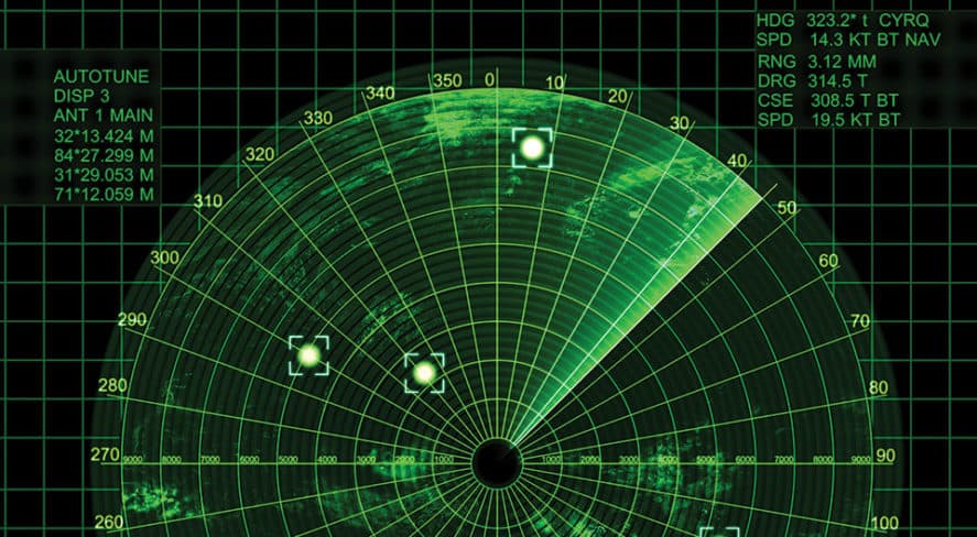
In fact, we use these coordinates when we need to analyze/use the motion of an object, to solve certain equations, a lot in aviation systems (like a radar that determines the position of a Plane(Radius, θ) in the sky). Why do we use it ? To stay accurate 
If needed you can also convert the 2D coordinates to world space before you do this conversion all you need is the inverse of the view and projection matrix. and since the grid is in 2D you can assume a depth of 1.0 for all points.
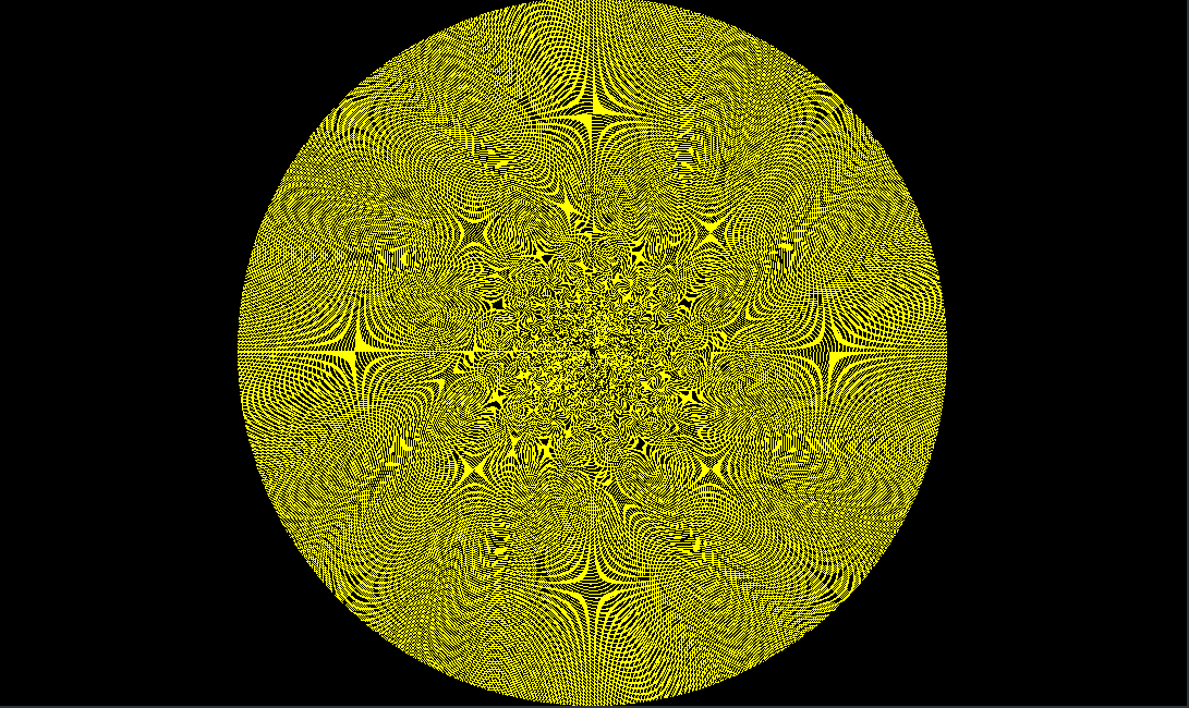
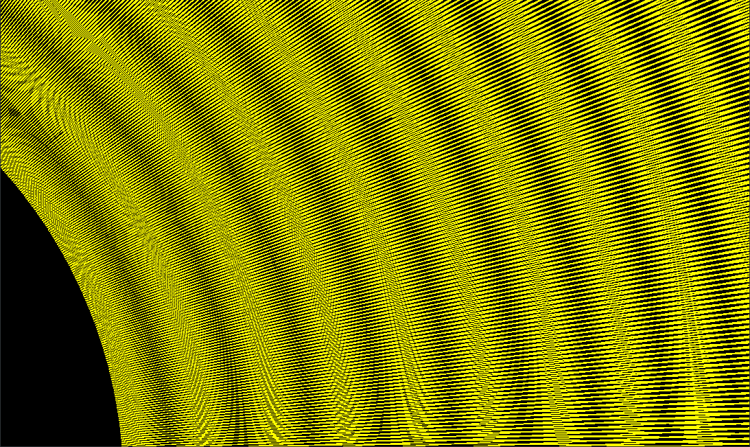
I did something similar to display my grid. When the program is starting a method is called during the initialization in order to calculate the cartesian coordinates of each cell of my grid. Once done we simply display these coordinates which make a circle. Here’s how it works :
- calculateRadarData() : Method called in initializeGL() where we calculate the cartesian coordinates of cells
- initializeGL() : Storage in VBO_GRID the cartesian data
- paintGL() : Display the VBO_GRID
void HelloGLWidget::calculateRadarData()
{
    radarData.resize(AZIMUTS, std::vector<QVector3D>(CELLS_PER_AZIMUTS));
    for (int azimut = 0; azimut < AZIMUTS; azimut++)
    { //For each azimut (angle) of my circle
        double theta = (azimut*2*M_PI)/AZIMUTS; //Conversion azimut to radians
        for(int cell = 0; cell<CELLS_PER_AZIMUTS; ++cell)
        { //for each cell of each azimut
            double D = CELL_DUR * (START_RG+cell) * c/2.0; //get the distance between the center and the cell
            double x = D*cos(theta); //get the x
            double y = D*sin(theta); //get the y
            radarData[azimut][cell] = QVector3D(x,y,-2); //storage in radarData with a depth of -2 (why not haha)
        }
    }
}
void HelloGLWidget::initializeGL()
{
    initializeOpenGLFunctions();
    glMapBuffer = reinterpret_cast<PFNGLMAPBUFFERPROC>(QOpenGLContext::currentContext()->getProcAddress("glMapBuffer"));

    glEnable(GL_DEPTH_TEST);
    glClearColor(0.0f,0.0f,0.0f,1.0f);

    shaderProgram.addShaderFromSourceFile(QGLShader::Vertex, ":/vertexShader.vsh");
    shaderProgram.addShaderFromSourceFile(QGLShader::Fragment, ":/fragmentShader.fsh");
    shaderProgram.link();

    glEnable(GL_MULTISAMPLE);
    glEnable(GL_LINE_SMOOTH);
    glHint(GL_LINE_SMOOTH_HINT,GL_NICEST);

    calculateRadarData(); //Get the cartesian coordinates of cells

    /* ....VBO_COLORS part ....*/

    /*VBO POLAR 2D GRID*/
    glGenBuffers(1,&VBO_GRID);
    glBindBuffer(GL_ARRAY_BUFFER,VBO_GRID);

    /*Move of the cartesian coordinates into the VBO_GRID*/
    std::vector<GLfloat> vertexData;
    for(const auto& azimut : radarData)
    {
        for(const auto& point : azimut)
        {
            vertexData.push_back(point.x());
            vertexData.push_back(point.y());
            vertexData.push_back(point.z());
        }
    }
    glBufferData(GL_ARRAY_BUFFER, vertexData.size()*sizeof (GLfloat), vertexData.data(), GL_STATIC_DRAW);

}
void HelloGLWidget::paintGL()
{
   glClear(GL_COLOR_BUFFER_BIT | GL_DEPTH_BUFFER_BIT);

    QMatrix4x4 mMatrix;
    QMatrix4x4 vMatrix;

    shaderProgram.bind();
    shaderProgram.setUniformValue("mvpMatrix", pMatrix * vMatrix * mMatrix);
    shaderProgram.setUniformValue("color", QColor(Qt::blue));

    glBindBuffer(GL_ARRAY_BUFFER,VBO_GRID);
    int vertexLocation = shaderProgram.attributeLocation("vertex");
    shaderProgram.enableAttributeArray(vertexLocation);
    glVertexAttribPointer(vertexLocation,3,GL_FLOAT, GL_FALSE,0,0);

    glLineWidth(0.01f);
    glDrawArrays(GL_LINE_LOOP,0,AZIMUTS*CELLS_PER_AZIMUTS);

    shaderProgram.disableAttributeArray(vertexLocation);

    shaderProgram.release();

}
To be honest I don’t know how to use the shaders to calculate from one of them all the 2D grid and make a texture from that by letting me “access” the color of cells that sould be update with the VBO_COLORS. I will check the link you’ve sent and show you what I can do.
Again I am not sure if I am missing any details but if you learn how to use compute shaders I am sure the logic of what you were doing before can be applied there. I am also a little confused as to why you need such a large grid but if its necessary this is something that can benefit from GPU parallelization.
I need to quickly create a kind of radarView. I receive some data that I decode for display. But as you’ve seen I’m absolutely a beginner in OpenGL (even if I spent just a few hours on it this month), also I have nobody around me to help me with OpenGL.
If you’re interested in the project I can share it
Now this is what I will try to do :
- Create a shader where I determine the polar grid 2D (to make it faster)
- Create a texture ?
- Associate the colors in the VBO_COLORS to each cells
I would be happy to hear some other advice, many thanks again !