Perspective projection without projection matrix

Hello! I ran into a problem with writing shader code correctly.

I used to always write shaders like this:

  • Vertex shader:
#version 330
    in vec3 in_vert;
    in vec4 in_color;
    
    out vec4 o_color;
    out float distance;
    
    void main() {
        vec3 rpos = in_vert;
        gl_Position = vec4(rpos.x, rpos.y, rpos.z, rpos.z);

        o_color = in_color;
        distance = rpos.z;
    }
  • Fragment shader:
#version 330
    
    in vec4 o_color;
    in float distance;
    
    out vec4 f_color;
    
    void main() {
        f_color = o_color;
        gl_FragDepth = distance;
    }

But it soon became clear that using gl_FragDepth seriously reduces performance (up to 10 times in the worst case).

I’ve read that you usually need a projection matrix when creating a perspective, but I didn’t like the presence of a near plane in it.
I just want all objects to be drawn between 0 and 1 in the Z coordinate, and the perspective matrix just doesn’t allow me to achieve the same result. Perhaps only within 0.000001 to 1, but it does not suit me at all.

The whole problem here is concentrated in gl_Position in the vertex shader.
I need to do all the transformations in gl_Position to get a perspective projection without a projection matrix.

I tried to do the following in the vertex shader:
gl_Position = vec4(rpos.x, rpos.y, pow(rpos.z, 2.0)*(rpos.z/abs(rpos.z)), rpos.z);
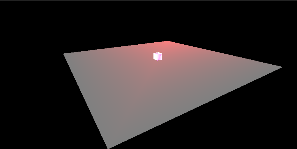
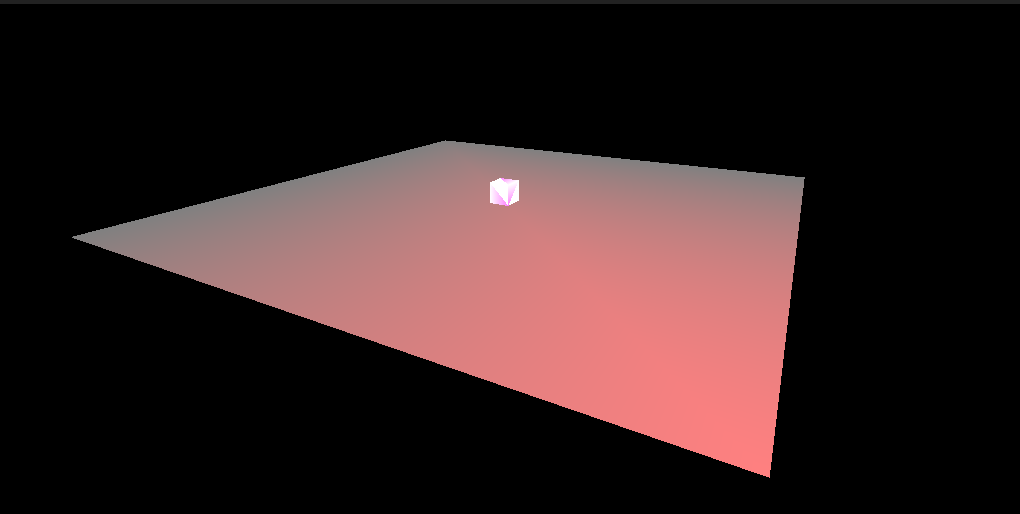
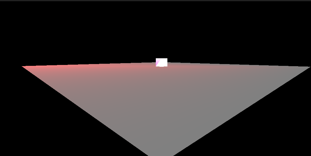
However, the problem was not solved and there were many errors with the DEPTH_TEST parameter enabled when approaching an object.
Does anyone know how to create perspective with gl_Position at [0 <= Z <= 1] ?

You can’t get linear depth without explicitly writing to gl_FragDepth, and (as you’ve noticed) writing to gl_FragDepth can be expensive.

Trying to do it by linearising gl_Position.z will result in primitives not depth sorting correctly (far surfaces can obscure nearer surfaces).

So in OpenGL you can only draw clippings? It’s such a simple thing to draw from 0 to 1, why can’t OpenGL do this? There must be an easy way.

There is no “simple” way to divide by zero.

A camera-space Z of 0 represents a projection evaluation of the form X/0. This is not a well-defined mathematical operation. And since the projection is not defined, you can’t draw it.

@Alfonse_Reinheart
I checked my old code, where I use gl_FragDepth, there are no problems with this, OpenGL calculates everything perfectly.


The yellow end of the nearest triangle is at coordinates [-0.05, 0, 0], everything is fine.


And in this photo I stepped back a little.

I’m sorry, I put it wrong, I need [0 < Z < 1], without Z=0 and Z=1.
The problem is that I need to get any non-zero value in the depth buffer, but without the help of non-zero limit.
To put up with a similar problem and just make the projection matrix [0.001 < Z < 1], my paradigm does not allow me to corny, which I adhere to - any variable can have unlimited accuracy of its value. And that’s why I consider setting static “coefficients” to be a bad/inefficient way to solve a performance problem.

Thanks to everyone who joined the discussion for your comments.

Division by zero is undefined. And division by numbers close to zero will result in very large numbers which are likely to overflow the range of a fixed-point depth buffer.

Also, bear in mind that a perspective projection maps the equally-spaced values of a fixed-point depth buffer to unequally-spaced values in eye space; using too small a value for the near distance results in poor depth resolution for most of the scene. Approximately (*) half of all possible depth values are used for -Zeye values between the near distance and twice the near distance, with the other half used for values beyond twice the near distance. Similarly, approximately 90% of all possible depth values are used for -Zeye values between the near distance and ten times the near distance, with the other 10% used for values beyond ten times the near distance.

(*) If you construct the perspective transformation so the the far plane is at infinity, the relationship is exact rather than an approximation. The relationship between -Zeye and ZNDC will be strictly reciprocal so the proportion of depth values used for -Zeye values beyond N times the near distance is exactly 1/N.

Using a floating-point depth buffer will allow the near plane to be much closer to zero (but still not equal to it) while retaining a reasonably even spacing of depth values. In that situation, you should construct the perspective projection so that ZNDC is zero at the far plane and one at the near plane. You can also use glEnable(GL_DEPTH_CLAMP) to disable clipping against the near and far planes.

1 Like

@GClements Wow! Thanks a lot!
I used a projection matrix and removed gl_FragDepth from the shader anyway, however with glEnable(GL_DEPTH_CLAMP) there was no clipping, it’s just fantastic!
I created the matrix like this:

float f = 1;  // far
float n = 0.5;  // near
float projection_matrix[16] = {
        1,0,0,0,
        0,1,0,0,
        0,0,f/(f-n),1,
        0,0,-(f*n)/(f-n),0
};


3863 FPS instead of 3100!

I already thought I would have to put up with this problem, but your experience helped me, thanks again!

There is clipping; you just don’t see it. By using depth clamping, every sample whose depth value would exceed the clipping volume is clamped to the maximum value. That means that all of those triangles have the same depth value.

So while they will appear in front of everything else, they won’t be ordered with respect to each other.

Oh no… This is a serious problem.
Well, OpenGL disappointed me.

It’s not OpenGL that disappointed you; mathematics disappointed you.

If OpenGL had the option to turn off the Z/W division for subsequent operations on gl_Position, leaving only X/W and Y/W, then there would be no such mandatory use of a projection matrix that limits rendering.
This would allow us to use the same gl_Position = vec4(rpos.x, rpos.y, rpos.z, rpos.z) construct that I am currently using, but without the need to use gl_FragDepth.
And there would be a nice, simple API

It is this obligation to use a projection matrix when creating a simple perspective that disappoints me. In mathematics, it is quite possible to do without a projection matrix, unlike OpenGL. :confused:

You keep talking about a “projection matrix” as if that’s the problem here. How you compute the clip-space positions is irrelevant; your problem is with the definition of clip-space (and of subsequent spaces).

So you are hypothesizing that normalized-device coordinate space (the space after dividing by W) should not be a 3D cube on the range [-1, 1], but should instead have X and Y on the range [-1, 1], with Z should be on the range… what, exactly? Furthermore, the window-space Z (which is the space of the depth values) is on the range [0, 1] (technically, it’s on the range specified by glDepthRange, but the range near/far values are restricted to being [0, 1]). Mapping from NDC’s [-1, 1] to window space’s [0, 1] is pretty simple. But without having some fixed, known range, how do you map them to [0, 1]?

So… what do you want? What does Z even mean in this scenario? What is post-projection space? Is it 3D, or 2D?

So yes, it seems to me that you’re disappointed by math. By consistent math.

A projective transformation preserves planarity. If a set of points lie in a plane in eye space, they also line in a plane in NDC. So NDC Z is an affine function of NDC X and Y, and depth is an affine function of window-space X and Y. This means that projective division (division by W) can be deferred until the point that you need to perform perspective-correct interpolation of attributes (texture coordinates, colour, etc). And if you don’t need to do that (e.g. because the depth test or stencil test fails, or you’re using flat shading, or noperspective interpolation, or whatever), the division can be skipped entirely.

In the early days of 3D hardware (when many of the conventions used by OpenGL and Direct3D were taking form), this was a significant issue for performance.

It isn’t the case if you divide X and Y by W but don’t divide Z; the resulting surface will be non-planar and requires a division per pixel just to calculate the depth.

Note that OpenGL (or rather, the hardware to which OpenGL provides an interface) at the per-fragment stage isn’t generating clip coordinates and transforming those to NDC and then window coordinates; it’s doing the reverse: enumerating window coordinates which lie inside the primitive (i.e. rasterisation) then reverse-transforming those to NDC (generating Z from X,Y via a plane equation) then to barycentric coordinates which are used to interpolate attribute values.

If you want linear depth, you can do it in the fragment shader using gl_FragDepth and pay the cost (which is dictated by the maths).

1 Like

@Alfonse_Reinheart
3D graphics engine, relative to the monitor X - horizontal axis, Y - vertical axis, Z - frame depth. Now we are talking about a camera with a perspective projection in the engine, so far the rendering is going on approximately as I indicated in the first post.

Z will initially have a range of [0, inf] where point 0 is the camera position, however it will be limited to the cleared depth texture value, i.e. 1 by default, so it will range from 0 to 1, as you actually said.

If you create a cube model with vertices at the limit values XYZ (1,1,1), (-1,-1,-1) and so on, then it turns out that the camera is located exactly in the middle of the cube, at the point (0, 0, 0) .

@GClements
You talk about the normalized NDC space as the ultimate technology, but why is it needed? If there are any problems with linear depth near, then you probably just need to calculate the square of the depth, and then, when reading, find the square root of the value. Isn’t that how they do it?
And the barycentric coordinates look somehow complicated and I don’t understand why this is needed.
The calculation of the perspective projection basically goes like this:
We have a vertex at position (0.2, 0.2, 0.5), we need to perspective project it onto the 2D camera texture.
X=X/Z
Y=Y/Z
Z=Z
And here we have it - a point (0.4, 0.4, 0.5).
The X, Y axes are drawn on the texture (within [-1, 1]), and the Z axis value is simply written to the depth buffer. Here’s how it works and no projection matrices.

In my opinion, projection matrices only write the Z value to the W variable and work a little with near and far on the Z variable itself. They can control the field of view, but this is a simple XY multiplication by a calculated angle multiplier, which is calculated through the tangent.

Maybe barycentric coordinates are needed to correct textures when they are deformed relative to the camera? No, it seems to be much easier to do.
It feels like the best mathematicians worked on OpenGL, they made everything difficult, but as a result, I can’t draw too close to the camera.

I don’t use distance kilometers or anything like that in my engine and I’m already used to the max (1, 1, 1) and min (-1, -1, -1) coordinates you call barycentric. I just don’t need to convert the coordinates to NDC since the whole engine is already built on them.

Projection matrices just allow you to make conditional kilometers of distances, which I simply visualize at the same time, dividing the coordinates of the vertices of all objects (relative to the camera), say, by the number 1000 and get the same result.

Projection matrices are the only thing that disappoints me about OpenGL. Because of this, I have to use gl_FragDepth at a performance cost, which is frustrating.
And yes, @Alfonse_Reinheart, math disappoints me, the way it is used.

glEnable(GL_DEPTH_CLAMP) is the only way for me to somehow fix the situation with the near planes of the projection matrix.

So you’re doing all of the projection math on the CPU? That’s also going to impact perspective-correct interpolation. In that you won’t have any.

Projection matrices just allow you to make conditional kilometers of distances, which I simply visualize at the same time, dividing the coordinates of the vertices of all objects (relative to the camera), say, by the number 1000 and get the same result.

No, you don’t get the same result. Either you’re somehow working in a post-projection space, or you’re doing more than dividing by a constant integer.

I rarely do calculations on the CPU. I do everything related to calculations in shaders (so as not to drive data from the video card to RAM and back). I wouldn’t call it a projection math, I just divide everything by 1000.

Hmm… I walked around the triangles and did not notice any mistakes - I go to the yellow top and see more yellow, step back and see that red prevails. It seems that OpenGL itself interpolates them. I just slightly modified my first example by adding a division of the vertex coordinates by 1000.

If you divide all the coordinates of all vertices (relative to the camera) by one number, for example, by 1000, then you will not see changes on the screen, but the rendering distance will increase significantly, which is noticeable if you step back, I additionally made sure of this.


No division by 1000


Divide by 1000


Divide by 1000 and step back

And with the correct interpolation of vertex colors, everything is fine, OpenGL draws it as always, perfectly.

But do you actually know “mistakes” to look for? I had to construct a very specific example to be able to show off the difference between perspective correct interpolation and non-perspective correct interpolation.

And in fact I do see a problem. Look at your “Divide by 1000 and step back” version. See how the triangle is half-orange? If you look at either of the top two versions, most of the orange is crammed into the right side of the triangle.

That doesn’t represent how things would look in an actual environment. Outside of doing actual lighting computations, moving away from an object should not change how colors interpolate across its surface.

Also, I notice that your examples of a scene with functioning perspective always seem to consist of… two triangles. Not even two triangles arranged in a plane or anything. Just two triangles in a void. How do you know that you’re achieving an actual perspective projection?

Show a floor plane with objects on top of it and a camera that can move to arbitrary positions.

Now I have made a cube on a plane. The plane consists of two triangles, and at the junction of these triangles, in the corner, I gave them a red color RGB(1, 0.5, 0.5).
The cube is adjacent to the plane.

Added a rotation matrix to rotate the camera.

Here everything is divided by 1,000,000.


Everything is drawn as it should and there are no distortions.

Except for the same distortion I pointed out before: the interpolation shown in the bottom picture is not perspective-correct.