Self shadowing issues

For some reason I can’t figure out why I am getting this self shadowing effect even when I am culling the front faces to prevent self shadowing. Maybe from looking at this sample you can tell what is actually happening here…

I am using an orthographic projection as such
glm::ortho(-1000.0f, 1000.0f, -1000.0f, 1000.0f, 1.0f, 10000.0f)which I am worried that potentially the near and far plane could cause depth buffer issues. I am then using
glm::lookAt(lightPosition, glm::vec3(0.0f), glm::vec3(0.0, 1.0, 0.0)) which orients the orthographic projection to the light’s direction.
My depth texture resolution has a very high resolution which is 8 times the size of the resolution of my viewport. Increasing the resolution of the depth texture improves the resolution of the shadows for me. I then cull front faces and draw the vertices in my shader and store it to the framebuffer which is attached to a texture.
I can display my depth texture and everything looks fine…perfect actually. I then switch back over to back face culling and do the actual render. What bothers me is that the landscapes do not seem to suffer from self shadowing while the sphere and rocks suffer from this “self shadowing”.
One thing I know is that the landscapes are planes which I am either looking at it’s back or front plane while the rocks and spheres will always have possible back and front planes from any orientation looking at them. Any ideas will help. I’m glad I fell upon this problem because it taught me a lot about how shadows are created but this is just not fun anymore.
Thanks
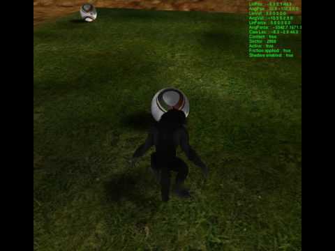
Interesting problem. There’s definitely something strange going on with your shadows. When you look at where the shadows are cast, what should be the “light sides” of your character and the ball are actually the dark sides. It’s like (for the purposes of casting those shadows into the shadow map) that the light is flipped 180 degrees, facing the exact opposite direction that is actually casting (if the position of the shadows cast on the ground is “correct”).

Are you sure that all of your casters lie solidly without your light’s frustum?
You’re not changing glFrontFace are you? You’re just flipping glCullFace and enabling GL_CULL_FACE.
Are you sure your shader position math when you’re projecting shadows onto your scene objects is correct?

However, before you start believing that casting back faces only into your shadow map is the solution to all of your self-shadowing problems, look at this. This doesn’t look like what you’re fighting with now, but it’s a limitation of casting only back-faces into the shadow map. You might instead read up on normal offset shadow mapping.

At first my thought was the same that the light direction must be negated and thus the light direction would be coming up through the floor but I tried to flip the light direction and then I didn’t get any shadows. I did notice that when i tested a small plane composed of two triangles that shadows would only be cast based based on it’s orientation. If I rotated the plane around the z axis I would only generate shadows from 360 to 180 and from 180 to 0 I get no shadow. I believe this is due to the fact that opengl decides which side is front or back based on my vertex model winding and therefore when culling, one side will never be visible. If my previous statement is true then culling is a problem for any geometry that is a plane and you can potentially look at that plane in any orientation…a way to get a around this I guess is to make thin walls ie rectangles for walls.

I am pretty sure that my geometry is within my light’s frustum. Did I answer that correctly?

Not changing windings using glFrontFace. I always have culling enabled but I flip to glCullFace(GL_CULL_FACE) when depth testing and then back to glCullFace(GL_CULL_BACK) when rendering scene.

This is where I think my problem may be. I transform my vertex using the lightModelView multiplied by the bias matrix which converts [-1, 1] ortho space to [0, 1] texture space in the vertex shader to generate shadow coordinate.
In the fragment shader I scale the shadow coord by it’s w value which is converting from clip space to normalized space. Do I need to first scale by clipping space then convert the lightModelView matrix with the bias matrix? Then I query my sampler2DShadow texture with my computed ShadowCoord divided by clip space. That value returned should be the distance from the light to closest found fragment in the depth test with front face culling. Then i just test to see if that distance is less than the sampler2DShadow value and if so then do not apply shadow.

[QUOTE=Dark Photon;1284485]
However, before you start believing that casting back faces only into your shadow map is the solution to all of your self-shadowing problems, look at this. This doesn’t look like what you’re fighting with now, but it’s a limitation of casting only back-faces into the shadow map. You might instead read up on normal offset shadow mapping.[/QUOTE]

I took a look at this and noticed some of my shadows do seem to be generated a bit in the front of the model when adding a bias. I also use a bias but noticed I would get significant shadows to leak out the other side and so i thought maybe the light direction was incorrect.

I went back to the drawing board because it was sort of difficult to understand how sampler2DShadow works. It is easier for me to understand comparing distances using the z depth value retrieved when querying the texture with an x y coordinate with the transformed vertex depth value. So I ripped out the sampler2DShadow and used a regular sampler2D and using this algorithm I can do some PCF calcualtions to make the shadows decent looking and less jagged.

vec2 texelSize = 1.0 / textureSize(ShadowMap, 0);
for(int x = -1; x <= 1; ++x)
{
for(int y = -1; y <= 1; ++y)
{
float pcfDepth = texture(ShadowMap, projCoords.xy + vec2(x, y) * texelSize).r;
shadowIntensity += currentDepth > pcfDepth ? 1.0 : 0.0;
}
}

The algorithm is simple where I compare the depth test distance with the projected distance of the current vertex and add or not add shadow. The shadowIntensity is divided by 9 after the loop because I take 9 samples.
This seemed to solve my problem by just redoing the work with sampler2D instead of sample2DShadow. Self shadowing is pretty much eliminated except for my animated characters.
I would post my depth buffer picture but I can’t upload jpg images event though the insert image message says I can post jpg images. What?
I’m sure the self shadowing is just something I am forgetting with updating vertices during my shadow draw but I have to take a break…

sampler2DShadow simply compares the third component of the texture coordinates to the texture’s value according to the texture’s GL_TEXTURE_COMPARE_FUNC parameter. Note that in order to access a texture using one of the sampler*shadow types, its GL_TEXTURE_COMPARE_MODE parameter must be GL_COMPARE_REF_TO_TEXTURE and its internal format must be a depth or depth+stencil format.

The advantage of using a shadow sampler over performing the comparison yourself is that the implementation can perform the comparison prior to applying any minification or magnification filters, whereas applying such filters to the depth values then comparing the filtered result would be meaningless.

I don’t know if you mis-spoke, but this is definitely an error. Enable/disable cullface is glEnable( GL_CULL_FACE ) and glDisable( GL_CULL_FACE ), respectively. Changing which face is culled when GL_CULL_FACE is enabled is done by glCullFace( GL_FRONT ) and glCullFace( GL_BACK ).

You’re missing the light’s PROJECTION transform here.

If you start with a WORLD-SPACE position, you need to multiply by the light’s ModelViewProj aka MODELING * VIEWING * PROJECTION (to transform WORLD-SPACE to light’s CLIP-SPACE). Then comes the bias matrix to effectively take (what will be, post-perspective-divide) -1…1 NDC space to 0…1 texture space. And finally comes the perspective divide (if needed), which takes your scaled/shifted CLIP-SPACE to scaled/shifted NDC space (0…1) proper. You can let the GPU’s texturing hardware do this divide (via textureProj, formerly shadow2Dproj) or you can do it yourself in the shader … again, if needed.

I say “if needed” because that perspective-divide is only needed if you’re using a perspective projection (for your light’s PROJECTION transform). You’d use such a projection for a point light source. However, you said you’re using orthographic for your light’s PROJECTION transform, so you can just skip the perspective-divide in your case – it’s a no-op (divide by 1 == noop).

In the fragment shader I scale the shadow coord by it’s w value

Ok, you mean divide by the w value? You can, but with an ortho projection, your w value should be 1, which is a no-op.

Do I need to first scale by clipping space then convert the lightModelView matrix with the bias matrix?

I didn’t follow this. Scaling by spaces doesn’t make sense. And in the last part, if by “convert” you mean multiply, then yes except that you need the lightModelViewProj.

Then I query my sampler2DShadow texture with my computed ShadowCoord divided by clip space.

I assume by “divided by clip space” (which doesn’t make sense) you mean “divide by the w value” as you alluded to above to get to texture space.

Re sampler2DShadow, looks like GClements is helping you with this. If you use sampler2DShadow and thus use hardware texture compare, then you can let he hardware do the divide-by-w (using textureProj). However with an ortho projection, that’s a no-op so you can just use texture.

And what’s returned (when you have hardware depth compare on) isn’t a distance. It’s a 0…1 factor that’s a “percent of light not shadowed” value. 1 = totally not shadowed, 0 = totally shadowed. It can be fractional if you let the hardware do PCF lookups (and you can get this by setting GL_LINEAR on your texture min and mag filters.

Now if you wanted to do lookups into your depth texture and get distances back from the texture lookups in the shader, then you’d:

  1. Disable texture compare mode and 2) use a sampler2D instead of a sampler2DShadow to pass it into the shader. Then your texture sampling function would return a depth. This doesn’t allow you to use hardware PCF though (IIRC).

That light leak happens even if your math is 100% correct and you use 0 bias … if your object isn’t closed, convex, and doesn’t intersect anything else. The larger your shadow map texels are in world-space, the larger the light leaks will be. However, even insanely large shadow resolution won’t completely get rid of the artifact; that just makes it smaller. It’s an area that’s not covered by shadow texels.

For example, consider two intersecting planes, one casting a shadow onto the other. Draw some really big shadow texels with centerpoints on the casting plane. Notice that not all of the casting plane is shadowed by shadow texels. Now what happens down close to the intersection where the receiver plane “peeks” into one of these unshadowed areas.

I agree with you Photon that I don’t always make sense because I’m realizing I have a pretty weak foundation in understanding the gl pipeline and how to think in terms of orthrographic or projection and keep it all together.
I was looking at video games (Skyrim) to see how they implemented directional shadow mapping and keeping it high resolution and always in the view matrix. I figured I just needed to translate the orthographic light frustrum to the camera position. I got it to work but I’m not sure if my previous reasoning is correct to get the shadows relative to the camera location. What helped a lot is visualizing the depth texture in the top left corner of my viewport to see how my translation of the ortho frustum worked. Here is a video to show you what I have working but I would like to point out at the end of the video you can still see a little bit of self shadowing on the werewolf…https://www.youtube.com/watch?v=KqHgCVW7RKQ&feature=youtu.be

For just starting out, you’re doing great! To make your life easier, you might do a little more reading on OpenGL Coordinate Spaces and the transforms that move you between them (I’ve listed a few links below). For the 5 minute overview, just review and memorize the left half of this diagram from Paul’s Shadow Mapping Project (the right half is the same thing – just for the light rather than the camera). Blue boxes represent coordinate spaces. Red-text links denote the transformations that take you between those coordinate spaces:

The green line represents the transformation you’re typically building for shadow mapping. Once you have that, just tack on the bias matrix (i.e. -1…1 -> 0…1 scale/shift matrix) and you’re done.

A few OpenGL transformation links to read when you get time:

Here is a video to show you what I have working but I would like to point out at the end of the video you can still see a little bit of self shadowing on the werewolf…https://www.youtube.com/watch?v=KqHgCVW7RKQ&feature=youtu.be

Looks good! I’m not sure what you mean about self-shadowing on the werewolf. It “should” self-shadow, right? I mean, if there’s a back-face on the character (e.g. back of the arm), it should cast shadows onto parts of the character that are further from the light.

Lighting makes it hard to see what’s going on. To see what’s going on with the shadows, you might change your shader to comment out the lighting code and just make your fragment color the value of the shadow map lookup + depth compare result (i.e. white = unshadowed, black = shadowed).

[QUOTE=Dark Photon;1284508]
Lighting makes it hard to see what’s going on. To see what’s going on with the shadows, you might change your shader to comment out the lighting code and just make your fragment color the value of the shadow map lookup + depth compare result (i.e. white = unshadowed, black = shadowed).[/QUOTE]

I switched my shader to black or white if the shadow is present or not and the answer was right in front of me and something I have been trying fix for a little bit now. The problem is geometry that overlap each other by a tiny amount and z fighting occurs which leads to a flashing or stitching effect. I believe you actually gave me a similar example where you talked about intersecting planes and at the intersection point there would be shadow leakage because the fragment depth value would be the same and one would have to be chosen as the depth value. But if they are being front face culled then I believe this issue shouldn’t appear which still leaves me perplexed…unless the triangles are not winded properly and openGL thinks they are back facing. I did not create the 3D models so I don’t know if they have consistent winding…I wonder if MAYA has an option to edit triangles to wind them all CCW or CW.

For a closed surface with consistent winding, every edge will occur exactly twice, once in one direction and once in the other. So if a you have a triangle with vertices 0,1,2, it has edges (0,1), (1,2), (2,0), and the edges (1,0), (2,1), (0,2) should each occur in exactly one triangle. If an edge occurs twice and both occurrences are in the same direction, the winding is inconsistent.

To fix it, you can start at a particular triangle then “flood fill” by examining adjacent triangles (those which share an edge), and inverting their winding if it’s inconsistent. If you discover that two “fixed” triangles are inconsistent with each other, then you have a non-orientable surface (such as a Moebius strip or a Klein bottle).

Determining whether the object is inside-out (i.e. whether the inside or outside faces are clockwise) is less straightforward. The simplest way I know of is to choose any point outside the surface (e.g. a point outside its bounding box) and and the centroid of any triangle such that the first point doesn’t lie in the plane of the triangle. That line will intersect the surface at least twice. Find the closest triangle to the first (outside) point which the line intersects. The side which faces toward the outside point is the outside.