Fragment position in light space (For shadow mapping) problems with Deferred Renderin

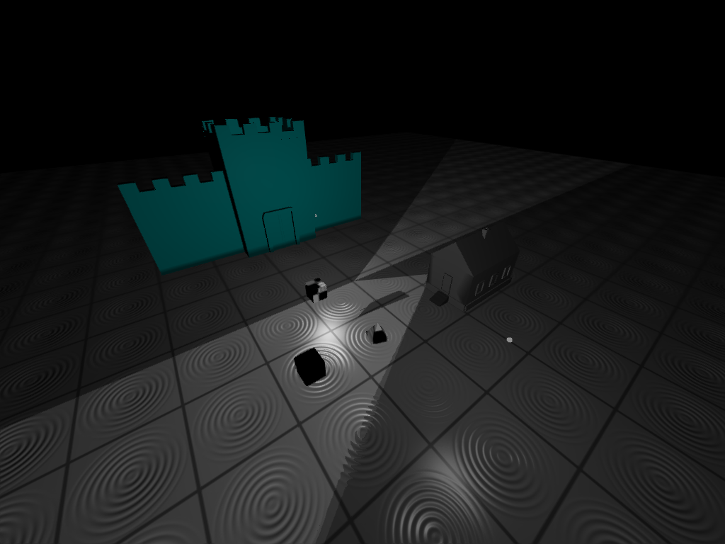
So I’ve been trying to get shadow mapping to work for what feels like an eternity now. Looked all over and even asked on Stack Overflow to no avail. My shadow map renders properly it seems (I would show pictures but this forum and stackoverflow make it needlessly difficult to share information beyond text) so I have come to the conclusion that the problem lies with my fragment positions in light space. I read somewhere that the process of fetching the frag positions in light space is a bit different with deferred. Since I’m storing the values in a texture. But I have no idea how to fix it since I can’t find any information on it. All tutorials that I have found do shadow mapping with forward rendering.


float shadowCalc(vec3 lightDir)
{
	vec4 fragPosLS = texture(gFragPosLS, uvs);
	vec3 projCoords = (fragPosLS.xyz / fragPosLS.w) * 0.5 + 0.5; //Manually do perspective divison
	float shadow;

	if(texture(shadowMap, projCoords.xy).r < projCoords.z)
		shadow = 0.4;
	else
		shadow = 1.0;

	return shadow;
}

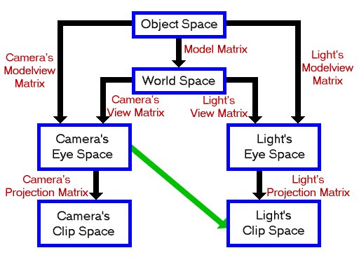
Here is my shadow calculation in the shader. gFragPosLS is a texture I send in which stores all the fragments in light space which I get like this:


vs_out.FragPosLS = LSMat * vec4(position, 1.0f); //Fragment position in light space

The LSMat is a uniform that represents the lightspace matrix which looks like this:


//Create LSMatrix
	GLfloat near_plane = 1.0f;
	GLfloat far_plane = 10.0f;
	glm::mat4 lightProjMat = glm::ortho(-10.0f, 10.0f, -10.0f, 10.0f, near_plane, far_plane);

	glm::mat4 lightViewMatrix = glm::lookAt(glm::vec3(-2.0f, 6.0f, -1.0f),
												glm::vec3(0.0f, 0.0f, 0.0f),
												glm::vec3(0.0f, 1.0f, 0.0f));
	shadowBuf.lightSpaceMat = lightProjMat * lightViewMatrix;

So as I said, I suspect the problem lies with how I read the fragment pos lightspace within the light pass. I’m just using regular uv coordinates that I use for everything else but seems like you can’t do that? Any help would be greatly appreciated and if I need to show more code or anything to make it clearer just tell me and I’ll upload more. Thanks.

That’s just because you’re a new user on this site. Certain features including post pictures and URLs aren’t allowed for new users until they’ve made a few posts. This is to prevent spammers from frequenting the site and posting junk under new user accounts.

…so I have come to the conclusion that the problem lies with my fragment positions in light space. I read somewhere that the process of fetching the frag positions in light space is a bit different with deferred.

Slightly but not much. It’s the same process to go to light space. But with deferred, there’s an extra step at the front.

With forward, you’ve computed the 3D fragment’s position in whatever space you want in your fragment shader (world-space, camera’s eye space, etc.). So you do your transform to light space from there (e.g. camera’s eye-space -> light’s clip space).

With deferred, you first need to fetch or reconstruct the 3D fragment position from data you’ve stored in your G-buffer (e.g. to get a position in camera’s eye-space). Then you apply the normal “to-light-space” math to the result.

See this image from Paul’s Shadow Mapping Project for a good diagram of how the spaces work:

Since I’m storing the values in a texture. But I have no idea how to fix it since I can’t find any information on it. All tutorials that I have found do shadow mapping with forward rendering.

It’s easy.

Step 1: Fetch (or reconstruct) the 3D fragment’s position in camera’s eye-space, and
Step 2: Transform this position to light’s clip space.

From your code, presumably you know how to do Step 2.

For Step 1, you need to provide how you’ve got position stored in your G-buffer. If you have just a 0…1 camera’s window-space depth value, there are a number of ways to get your camera eye-space position back from that. Here’s one. See PositionFromDepth_DarkPhoton() in this post.

The LSMat is a uniform that represents the lightspace matrix

One minor beef with this. Transforms (e.g. matrices) are not “in” coordinate spaces. They take you from one space to another. From the code LSmat implicitly takes you from “some space” to the light’s clip space. However, there’s no clue here what “some space” is.

A better name (if true) would be: EyeToLightClip or CameraEyeToLightClip.

Thanks for the reply.
So should I call the LSMat for something along the lines of ModelToLightClip since it affects vertices I fetch from the model’s file?

I have all of the fragment positions stored in a gbuffer texture called gPosition which I can easily sample from. Am I supposed to fetch that coordinate and then multiply it with the LSMat in the lightpass? (Adding the LSMat as a uniform in the lightpass’ fragment shader instead of the geo pass vertex shader) Because I think that would end up being the same thing as I’m doing now, except at a later stage. I’ve seen several different methods across various tutorials and it is part of the reason why I’m so confused.


LearnOpenGL says it should be like this:
       vs_out.FragPos = vec3(model * vec4(position, 1.0f));
       vs_out.FragPosLS = LSMat * vec4(vs_out.FragPos, 1.0f); //Dunno which one is correct

Another tutorial says it should be like this instead: (Which is what I currently have)
	vs_out.FragPos = vec3(model * vec4(position, 1.0f));
	vs_out.FragPosLS = LSMat * vec4(position, 1.0f); //Fragment position in light space

But I’m wondering if I should be multiplying it with the model matrix because some oddities appear when I do it like I currently am. Again, I really wish I could just show a picture but that’s not happening.

Anyways from what you are telling me I’m not supposed to do the fragmentposLS step at all in the vertex shader and instead do it in the lightpass fragment shader? But again like I said, won’t that end up being the same thing?

[QUOTE=Tobothy;1283567]Thanks for the reply.
So should I call the LSMat for something along the lines of ModelToLightClip since it affects vertices I fetch from the model’s file?[/QUOTE]

It’s your call. But if you name it based on the space it transforms you from and to, then ObjectToLightClip, WorldToLightClip, or EyeToLightClip would be good. I’d pick the one that reflects the correct starting space.

What is the correct starting space for LSMat as the code is currently written?

I have all of the fragment positions stored in a gbuffer texture called gPosition which I can easily sample from.

Full 3D positions? In which space – camera eye-space?

Am I supposed to fetch that coordinate and then multiply it with the LSMat in the lightpass?

If the coordinate space that your gPosition is in is the same as the starting space for your LSMat transform, yes.

If not, you’ll have to transform gPosition to the starting space for your LSMat transform first. Or possibly even better, feed in your LSMat so it just accepts coordinates in that space with no intermediate space conversion required.

What space is gPosition in, and what is the source space for the LSMat transform?

LearnOpenGL says it should be like this:
vs_out.FragPos = vec3(model * vec4(position, 1.0f));
vs_out.FragPosLS = LSMat * vec4(vs_out.FragPos, 1.0f); //Dunno which one is correct

If “model” is a MODELING transform (which transforms OBJECT-SPACE positions to WORLD-SPACE), then vs_out.FragPos is WORLD-SPACE. So the second line implies that LSMat transforms positions from WORLD-SPACE.

Another tutorial says it should be like this instead: (Which is what I currently have)
vs_out.FragPos = vec3(model * vec4(position, 1.0f));
vs_out.FragPosLS = LSMat * vec4(position, 1.0f); //Fragment position in light space

Same first line. But the second line implies that LSMAT transforms positions from OBJECT-SPACE (instead of WORLD-SPACE). You very likely aren’t storing OBJECT-SPACE in your G-buffer.

Again, I really wish I could just show a picture but that’s not happening.

Post the picture on some picture sharing site, and then just post a link to it here. To get the forums to take it, you may have to remove the http://, add a space or two to the URL, etc. Just do that, and I’ll fix it up to point to the actual picture when I see your post.

Anyways from what you are telling me I’m not supposed to do the fragmentposLS step at all in the vertex shader and instead do it in the lightpass fragment shader? But again like I said, won’t that end up being the same thing?

I don’t think I said that.

Tell you what. Please describe exactly what (at a high level) are trying to do to integrate shadow mapping with deferred rendering. You have options here.

From your description, I inferred you were trying to sample and apply your shadow map in the deferred lighting pass(es) – after you’ve sampled your scene into the G-buffer in the geometry pass. Is this what you’re trying to do?

Alternatively, you could sample your shadow map during the G-buffer geometry pass and store the shadowing value in a G-buffer channel for application later.

Which of these are you trying to do (or are you aiming for something else)?

My bad, I guess I misinterpreted what you said.

My gPosition contains all the vec3s that are the FragPos vectors:


In the VS:
vs_out.FragPos = vec3(model * vec4(position, 1.0f)); 
In the Geo pass FS:
gPosition = fs_in.FragPos;

So that would be world space unless I’m mistaken because the position is multiplied with the model matrix which takes it from model space to world space.
After reading up on it my LSMat transforms world space vectors into light space. And since I’m doing it like LearnOpenGL then I suppose in my case the way he does it is the correct one for me. Like this:


vs_out.FragPos = vec3(model * vec4(position, 1.0f));
vs_out.FragPosLS = LSMat * vec4(vs_out.FragPos, 1.0f); 

Also are “Full 3D Positons” different from what I’m storing in my gPosition buffer which contains vec3s? Either way since my gPosition contains all of the Fragment positions in world space then I guess they are not in camera-eye space. Camera eye space would be when I multiplied it with the view matrix, if I’m not confusing all of the spaces, which I have been at times.

Describing what I’m trying to do on a high level would be that I render my scene to a shadow map, then I do the geometry pass and finally use the shadow map in the light pass. Sampling from it to determine which fragments should be darkened. Which sounds like the first thing you described out of the two options.

Update:
I remember uploading my shaders when I asked on stack overflow that might cover something I’m missing here. They are a bit of a mess since this is my first time using OpenGL but I hope it isn’t too bad.
Shadowbuffer creation: http://pastebin.com/J4PCZysg, Geo Pass Shaders: http://pastebin.com/wjpq00vE and finally Light Pass shaders: http://pastebin.com/TaVSDfSn
But I’ll be doing my best to try and solve it with what you have said so far. Experimentation can’t hurt. (Hopefully) :stuck_out_tongue:

Update #2:
If I’m looking at the picture you posted first. I should be doing something like this?:

    vs_out.FragPosLS = LSMat * view * vec4(vs_out.FragPos, 1.0f); //FragPos already multiplied with the model matrix so no need to do it again

Because that causes there to be a weird shadow that is stuck to the camera. Unsurprisingly because I’m using the camera’s view matrix. But at the same time the LSMat contains a lightviewmatrix and a lightprojection matrix. But I’m just trying to follow that image. Which I’m interpreting as first you multiply the position with the model matrix, once it is on world space you multiply it with the camera view matrix and then the lightspace matrix. But maybe the problem lies in the fact that the LSMat is both a view and a projection matrix bundled together when in reality I’m only supposed to use the projection matrix from the view?

I feel like I’m just confusing myself at this point. Time for a break.

I see. So gPosition is world-space, and LSMat takes world-space to light’s clip space. Given that, it sounds like your position transformation logic should be right.

No. Same thing.

Describing what I’m trying to do on a high level would be that I render my scene to a shadow map, then I do the geometry pass and finally use the shadow map in the light pass. Sampling from it to determine which fragments should be darkened. Which sounds like the first thing you described out of the two options.

Right. Thanks for clarifying.

Update #2:
If I’m looking at the picture you posted first. I should be doing something like this?:

    vs_out.FragPosLS = LSMat * view * vec4(vs_out.FragPos, 1.0f); //FragPos already multiplied with the model matrix so no need to do it again

You would only do this if your LSMat transforms from “camera eye-space -to- light clip-space”.

You can generate LSMat in your app to take you from and to any spaces you want.

[quote]…that causes there to be a weird shadow that is stuck to the camera. Unsurprisingly because I’m using the camera’s view matrix. But at the same time the LSMat contains a lightviewmatrix and a lightprojection matrix. But I’m just trying to follow that image.

Don’t get caught up with the green arrow. Ignoring that, this diagram just shows the various coordinate spaces involved and the various transforms that take you from one space to the next.

With shadow mapping, the goal is to end up in light’s clip-space. However, you can start with a position in any one of these other spaces, and so long as you multiply your transforms together properly, you can get to light’s clip-space.

Yes, in this diagram the green arrow is proposing that you start with a camera’s eye-space position. However, you can just as well start with a world-space position if you want (as you’re doing now).

To come from camera’s eye-space, you’d use: LSmat = ( lights_projection * lights_view * inv_cameras_view )
To come from world space, you’d just use: LSmat = ( lights_projection * lights_view )

It appears you did the latter above. So that’s consistent.

But maybe the problem lies in the fact that the LSMat is both a view and a projection matrix bundled together when in reality I’m only supposed to use the projection matrix from the view?

No. There’s no problem “bundling” (multiplying) these matrices together. You get the same result in the end.

In other words, if A and B are matrices and v is a vector: A*(Bv) == (AB)*v

I feel like I’m just confusing myself at this point. Time for a break.

Sounds like you’re close and that your basic understanding is good. It’s probably something simple that you’ll smack your forehead about when you find. :slight_smile:

You might switch your camera rendering to ortho so it matches the view and projection you’re using for your shadow map. Then view your shadow map as a greyscale image. Do they seem to match?

I feel like I am annoyingly close to solving it. But it feels like the fragment positions are all correct then.

My shadowmap looks like this when rendered to the screen:

[ul]
[li]http://pahlavan.se/dump/Rostam_Rendering_2016-08-22_00-12-36.png[/li][/ul]
And when I use the shadow map orthographic and view matricies for the camera it looks like this:

[ul]
[li]http://pahlavan.se/dump/Rostam_Rendering_2016-08-22_00-13-51.png[/li][/ul]

Which looks almost the same but some triangles seem to vanish for whatever reason. (Don’t mind the screwed up textures it is just because I didn’t bother to UV map the meshes properly) You can also see the big incorrect shadow that goes across the screen instead of falling from the shadow map’s perspective. Which is really odd. Not to mention it only seems to affect the spinning pyramid in the middle. Also the black part that seems to be cut off from the top in the regular rendered view. I’ve tried tweaking the near and far plane to no avail but at least the shadow map renders properly. Or so it seems. I’m unsure what I’m doing wrong. I thought it was the light space fragment position which was incorrect but since we concluded that it transforms world space coordinates, which is what I’m supplying it. Then I have no idea what the problem is. :confused:

Two suggestions:

  1. Sanity check your coordinate system math visually.

That is, where you’d normally sample and apply your shadow map in your lighting pass, comment that out. Instead, take fragPosLS.xyz, and determine if it lies within a -1…1 cube. That is -1 < x,y,z < +1. If it does, make the fragment color magenta. If it doesn’t, use the color you’d normally output (sans shadowing).

This should allow you to clearly see the volume of the scene sampled by your shadow map, and you can verify that it “looks right”.

You can use this same “clipping” operation to determine whether to apply your shadow map to fragments in the scene. If it’s not in the box, then it should probably be treated as unoccluded (the exception of course being fragments that are behind the far clip plane of the shadow map which are occluded by samples in the shadow map, but that’s a minor optimization, irrelevant if your shadow bounds encompass all receivers).

  1. Simplify your test scenario down to something very simple, compute the expected result, and verify the actual result matches.

For instance, setup a directional (ortho) light shining directly down on a plane, where the near/far clip sandwich the plane exactly (e.g. near/far -1…+1, plane at +0). Compute exactly what the window-position depth value that gets written in the shadow map should be (0.5, in the case I described; the math is easy because eye-space near…far depth maps linearly to NDC’s -1…1 depth with an ortho projection, which maps linearly to 0…1 window space depth assuming glDepthRange of 0…1). Then run your code and verify that that is exactly what you get from the GPU, for all pixels in the shadow map.

Now apply that shadow to your scene (which is just one plane). Use a different viewpoint than the light’s position. You will likely see lots of Z-fighting on the plane, caused by your plane having been cast into your shadow map, if your shadow map construction and usage is right. You can use a little depth bias to shift the shadow map depth samples a bit to verify that the plane’s position (as sampled into the shadow map) is matching up exactly with the plane being rendered into your camera view.

I wish my engine wasn’t such a pile a spaghetti. But I managed to do the magenta test you described. The area covered by shadow map is colored but all of the “sky” and parts that aren’t covered by the shadow map are also covered. The colored part goes off into the distance the same direction the incorrect shadow appears in the picture above where I rendered the scene from the light’s perspective.

Not sure how helpful this picture is but. If you see those two white spots those are my lights and the little “bump” that sticks out from the magenta part is the house that is covered by the shadow map. If the fragposLS was correct then I would assume that there would have been a well defined box around the scene, but right now as you can see it is huge and stretches all over when in reality it should be a box centered around the middle of the scene. And like I said the angle seems to be the same angle that the incorrect shadow in the earlier picture is aligned with. So something is clearly afoot.
I didn’t realize becoming a graphics programmer meant you had to pick up some detective skills along the way. Since the plot is thickening.

The if statement I used to check is a bit wonky but it works unless I’ve forgotten how if statements work:


        if( 
    (-1 < fragPosLS.x && fragPosLS.x < 1)
    &&
    (-1 < fragPosLS.y && fragPosLS.y < 1)
    &&
    (-1 < fragPosLS.z && fragPosLS.z < 1))
    {
        return vec4(1,0,1,0);
    }

//Otherwise continues and returns regular color

I wanted to have a statement with -1 < fragPosLS.x < 1 but for some reason that wasn’t allowed. Which seems to be valid in C++ but I guess GLSL doesn’t like that.

I even tried just now turning the regular FragPos into a vec4 when it is stored in the gPosition buffer. Ignore the FragPosLS texture and send in the LSMat directly into the light pass. So my shadow calculation becomes this instead:


    vec4 fragPosLS = texture(gPosition, uvs) * LSMat; //Using gPosition vec4 instead of FragPosLS texture and multiplying with the LSMat to get a fragment in light space

    vec3 projCoords = fragPosLS.xyz / fragPosLS.w; //Manually do perspective divison
    //vec3 projCoords = fragPosLS.xyz; //Manually do perspective divison

    projCoords = projCoords * 0.5 + 0.5;

    float closestDepth = texture(shadowMap, projCoords.xy).r;
    float currentDepth = projCoords.z;
    float bias = max(0.05 * (1.0 - dot(texture(gNormal, uvs).rgb, lightDir)), 0.005); //Not used for now 
    float shadow = currentDepth - bias > closestDepth ? 1.0 : 0.0;

    return shadow;


But that ends up wrong too. Which eliminates the possibility of the problem lying with the FragPosLS texture, or well… not entirely since it looks different now:


Which hardly looks correct. This is becoming more and more frustrating. I wish I knew what the damned problem was but I just can’t figure it out. Maybe it is the LSMat but I posted the code for that before, it is identical to the one LearnOpenGL uses and he uses it just fine.

Edit:

So I spoke to a classmate who uses DX. He told me to render what I sample from the shadow map onto the screen to see what it looks like.

Here is what it looks like when I sample the FragPosLS texture: http://pahlavan.se/dump/Rostam_Rendering_2016-08-22_21-06-00.png Obviously looks wrong.
And here is what it is like when I sampled from the gPosition, got the world coordinate and used the LSMat in the fragment shader to go to light space:
http://pahlavan.se/dump/Rostam_Rendering_2016-08-22_21-01-29.png
Obviously not right either.

Supposed to be something like this: http://i.imgur.com/D2I0Uwe.png
The plot thickens again.