Hello
I am trying to code a UI for a homemade jukebox (with a touch screen).
I would like to display a background texture which size is the same as the screen to exactly fit to it.
That texture has nx by ny black boxes where the labels with the available songs will be displayed. I want these labels to rotate on their X axis when I change the page and they should, once again, perfectly fit to the boxes (when they are not turning).
I see how to display a 2D rectangle with this kind of vertex shader:
    vec2 vertexPosition = vPosition - vec2(screenwidth/2,screenheight/2); // ramener le 0,0 au centre de l'écran
        vertexPosition /= vec2(screenwidth/2,screenheight/2); // ramener les coordonnées sur un intervalle [-1;1]
        gl_Position =  vec4(vertexPosition,0,1);
But I can’t use that as I must display all that in 3D and then I don’t know how manage the (x,y,z) coordinates of the 3D vertices to be placed exactly where I want, to perfectly fit to the screen.
Any help would be appreciated.
Thanks
David
that’s a grammer-school problem.
Do make one box centered at (0,0,0) … then copy & add an offset to it’s proper place on the screen.
a texture cannot ‘have’ boxes like that. At best, the boxes may use/have/display a texture on it’s faces.
You provide presciously little info on your setup. I suspect that you’ll need to scale the screen to say match pixels … screenwidth is ie measured in pixels. To that end you should have a look at gl_viewport and an orthographic projection matrix.
If you draw indirect (say draw_elements() ) and use an index-buffer, then you can do with providing only 8 vertices pr box and then setup how they are to be combined in the indices (6 indices pr face to draw a rect). If each box needs it’s own set of texture-coordinates, then you have a new puzzel at hand, one that probably involves 3 tex-coords pr vertex.
After that, you’ll have to apply a rotation-matrix on each of the boxes … to make them rotate.
… you can also use draw_instanced(), but I cannot help you there.
Sorry, I have taken shortcuts, you’re right. I meant: I will display a title at the top, a menu at the bottom and then draw columns and lines separating the rectangles where the labels will be displayed to. So there will be real rectangle holes.
Not sure I understand the question, sorry? I display OpenGL3.3 elements in a full screen window using GLFW.
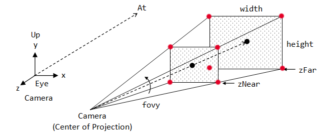
That’s exactly what I am looking for, calculating the scale. For example, if I could get the corner 3D-coordinates of the near and far rectangles declared via glm::perspective(field_of_view,ratio_height_per_width,z_near,z_far) (viewing frustum) showed in red dots here:
That would be very easy for me to get the corner coordinates for any parallel rectangle with z=k and then I would have the dimension of that rectangle giving me scaling factor I need. But I don’t know how to compute these 3D coordinates.
yes, that’s what I was looking for. Also the profile you have request makes a difference on what openGL capabillities you have access to.
If you havn’t looked at glViewPort() then please do. It’s a straightforward consept.
I’ll still suggest that you start out with an orthographic projection … it’ll take the same values as you put into the viewport … that’s the recipe for lining vertex-coordinates up scaled to pixels.
You can later focus on the projection and fiddle with exactly where to position the ‘eye’ to span the area you want to look at.
The view-matrix can be reduced to a pose (position and direction). If you use an identity-matrix, the eye will be looking in the -z direction from (0,0,0). So, cutting a corner there means that you’ll have to position your model at a xy-plane with some -z offset. Using the glm::lookAt() projection extends for you to consider the relative position of eye & model. You can zoom in and out by moving eye along the direction-vector eye->model.
Building your own viewMatrix usually is counter-intuitive. It’s a matrix that transforms the model-coordinates as they are expressed in world-space. So, if you think of the default camera, some matrix-transform can move the model to pose infront the eye. right? This frame-of-reference is called eye-space. If the original model starts out with some orientation in a position in-front of the eye( somewhere down z) and then are added another pose by a matrix-transform (new position & orientation in world-space), you’ll find that the view-matrix turns out to be the inverse-transpose of this matrix. Looked at through the eye, the model will not move anywhere if you use the view-matrix on the also moved model. But, if you have a background, it matters. You do the same conseptual thing if you only want to move the camera relative to the model.
The ‘world’ frame-of -reference is … intuitive … probably only exists in your head. The only way to ‘envision’ it is through an eye ;o( The eye-space has an inverted z-direction relative to this abstraction. The view-matrix primes the model for the projection-transform. The projection * view * model is one matrix.
…
I wonder if I’m clearing this up for you or for myself ;o/
The matrix generated by glm::perspective always has the form
Sx  0  0  0
 0 Sy  0  0
 0  0  C  D
 0  0 -1  0
where Sx=cot(fov/2)/aspect and Sy=cot(fov/2); C and D are determined from the near and far distances and don’t affect this calculation. Rather than calculating Sx and Sy, you should read them from the matrix generated by glm::perspective.
So you have:
xclip = Sx*xeye
yclip = Sy*yeye
wclip = -zeye
The edges of the view frustum are defined by the equations
xclip = -wclip (left)
xclip = wclip (right)
yclip = -wclip (bottom)
yclip = wclip (top)
In eye space, these become
Sx*xeye = zeye => xeye = zeye/Sx (left)
Sx*xeye = -zeye => xeye = -zeye/Sx (right)
Sy*yeye = zeye => yeye = zeye/Sy (bottom)
Sy*yeye = -zeye => yeye = -zeye/Sy (top)
IOW, just divide ±zeye by Sx and Sy to get the left/right/top/bottom edges in eye space. Note that zeye is negative for points in front of the viewer, i.e. -zfar < zeye < -znear.
I know about glViewport, if you mean that I should define a glViewport for each label to position it, the problem is that the aspect for the whole page will be wrong as each label will have its own projection in its “local” viewport.
You are right, I could first try with an orthographic projection, but anyway, the problem with such simple objects as labels turning on 1 axis, it will look terrible, I guess. Anyway, I’ll try, thanks.
Thank you GClements for your answer.
To make it definitely clear, the 3D coordinates in eye space of the bottom-left and top-right corners of the clipping rectangle for the plane at z=k are:
(k/Sx, k/Sy, k) and (-k/Sx, -k/Sy, k)?
Yes. Note that k should be the actual eye-space Z coordinate (which will be negative), not the distance “in front of” the viewer. Sx and Sy are normally positive so (k/Sx, k/Sy, k) will be all negative while (-k/Sx, -k/Sy, k) will be (positive, positive, negative).