Hello,
I’ve been trying to implement omnidirectional point light shadows using a depth cubemap, following the excellent tutorials on LearnOpenGL. I’ve run into a bit of a wall with rendering the cubemap. My gut feeling is that my problem is in the geometry shader; or possibly with the directional transform matrices that get sent to the GS to render to each of the cube faces.
First, some basic info on what I’m building. This application is OpenGL 4.5, with all shaders using version 450 core. I’m developing it in C# with OpenTK, and so far haven’t had any problems with the OpenGL bindings. I’ve also implemented a number of things like model loading, light bloom effects, geometry shader normal debugging (from the same excellent tutorial site) without any issues. I’ve done OpenGL apps a long time ago, but they were all in C++, immediate mode GL 1.x and I’ve never done shadow mapping before, so apologies in advance for the excessive number of RenderDoc screenshots you are about to behold.
Here is the OpenGL context information:
Version: 4.5.0 NVIDIA 442.50
Vendor: NVIDIA Corporation
Renderer: GeForce RTX 2060/PCIe/SSE2
Shading Language Version: 4.50 NVIDIA
The shadow depth cubemap (bound to a depth-only framebuffer) for the point light is generated as follows (verified this by inspecting the cubemap in RenderDoc):
- Size: 1024x1024
- Pixel Type: Float
- Pixel Format: Depth Component
- Pixel Internal Format: Depth Component 24
- S/T/R Wrap Modes: Clamp to Edge
- Min/Mag Filter: Nearest
OpenGL is using the following settings during the depth-only render pass, again verified in RenderDoc:
- Depth Test: Enabled
- Depth Write Enabled: True
- Depth Function: Less (Tried it with Always, same results)
- Depth Mask: True
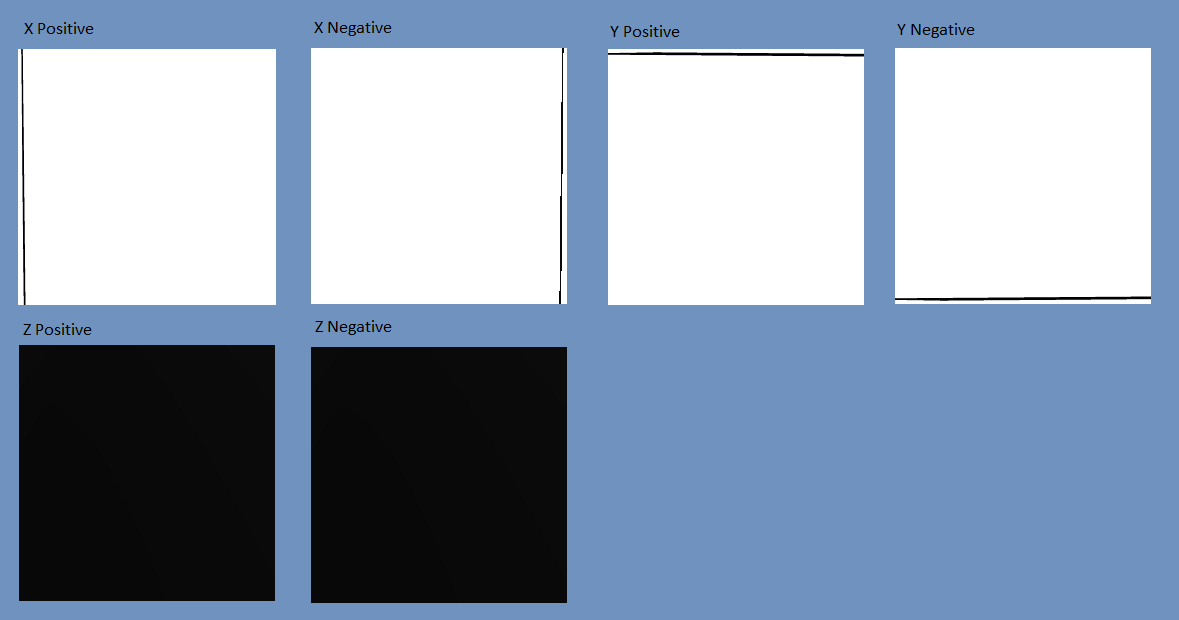
The problem was fairly obvious when I checked out the depth map in RenderDoc: It’s not generating anything close to what I’d expect. The depth values being written are mostly white (depth 1.0), with a black line along the edge of each face except for the positive and negative Z faces, which are black (depth 0.0). I’ve exported each face of the cubemap for debugging purposes here, scaled down a bit:
Depth-Only Vertex Shader:
    #version 450 core

    layout(location = 0) in vec4 vertexPosition;

    uniform mat4 modelMatrix;

    void main() {
    gl_Position = modelMatrix * vertexPosition;
    }
Geometry Shader (I’m setting gl_Layer explicitly as my graphics driver didn’t seem to like dynamically assigning it in a loop as in the tutorial code, I’ve also put each face transformation matrix as a separate uniform to make sure it wasn’t an issue with passing an array of mat4)
    #version 450 core

    layout(triangles) in;
    layout(triangle_strip, max_vertices = 18) out;

    uniform mat4 rightTransform;
    uniform mat4 leftTransform;
    uniform mat4 topTransform;
    uniform mat4 bottomTransform;
    uniform mat4 nearTransform;
    uniform mat4 farTransform;

    out vec4 fragPosition;

    void emitCubeFace(int layer, mat4 transform) {
        for(int i = 0; i < 3; ++i) {
            fragPosition = gl_in[i].gl_Position;
            gl_Position = transform * fragPosition;
            EmitVertex();
        }
        EndPrimitive();

    }

    void main() {
        gl_Layer = 0;
        emitCubeFace(0, rightTransform);
        gl_Layer = 1;
        emitCubeFace(1, leftTransform);
        gl_Layer = 2;
        emitCubeFace(2, topTransform);
        gl_Layer = 3;
        emitCubeFace(3, bottomTransform);
        gl_Layer = 4;
        emitCubeFace(4, nearTransform);
        gl_Layer = 5;
        emitCubeFace(5, farTransform);
    }
And the fragment shader:
    #version 450 core

    in vec4 fragPosition;
    uniform vec3 lightPosition;
    uniform float farPlane;

    void main() {
        float fragmentToLightDistance = length(fragPosition.xyz - lightPosition);
        // Map light distance into (0, 1) range
        fragmentToLightDistance = fragmentToLightDistance / farPlane;
        gl_FragDepth = fragmentToLightDistance;
    }
The code that generates those face transform matrices and sets up the shader values:
    // Each point light that casts a shadow needs to have a set of matrix transformations for each view direction (right, left, top, bottom, front, back)
    // These vectors are the target parameters for LookAt for each view direction
    var targetVectors = new Vector3[] {
        new Vector3(1, 0, 0),
        new Vector3(-1, 0, 0),
        new Vector3(0, 1, 0),
        new Vector3(0, -1, 0),
        new Vector3(0, 0, 1),
        new Vector3(0, 0, -1)
    };
    // These vectors are the up parameters for LookAt for each view direction
    var upVectors = new Vector3[] {
        new Vector3(0, -1, 0),
        new Vector3(0, -1, 0),
        new Vector3(0, 0, 1),
        new Vector3(0, 0, -1),
        new Vector3(0, -1, 0),
        new Vector3(0, -1, 0)
    };

    depthOnlyShader.Activate();

    GL.Viewport(0, 0, light.ShadowDepthBuffer.Width, light.ShadowDepthBuffer.Height);
    light.ShadowDepthBuffer.Bind(); // Bind the framebuffer
    var aspectRatio = (float)light.ShadowDepthBuffer.Width / (float)light.ShadowDepthBuffer.Height;
    var near = 0.01f;
    var far = light.ShadowFarPlane; // This is currently always set to 50.0f
    var lightPos = light.Position;

    var shadowProjection = Matrix4.CreatePerspectiveFieldOfView(MathHelper.DegreesToRadians(90.0f), aspectRatio, near, far);

    // Setup transform matrices in the following order: right, left, top, bottom, near, far
    var uniformNames = new string[] { "rightTransform", "leftTransform", "topTransform", "bottomTransform", "nearTransform", "farTransform" };
    for (int i = 0; i < 6; i++) {
        var viewDirectionTransform = shadowProjection * Matrix4.LookAt(lightPos, lightPos + targetVectors[i], upVectors[i]);;
        depthOnlyShader.Uniforms[uniformNames[i]].SetValue(viewDirectionTransform);
    }
    depthOnlyShader.Uniforms["farPlane"].SetValue(far);
    depthOnlyShader.Uniforms["lightPosition"].SetValue(lightPos);
    // Do the rendering
    // [...]
Unfortunately as a new user, I can only post one image, so I’ve placed the rest of the screenshots in an Imgur gallery: http://imgur.com/a/gP5lpB0
Description of the images in the gallery:
One image shows the actual matrix values being sent to the geometry shader from RenderDoc.
Another image shows the actual render (It has a light bloom effect applied, but I verified that the shadow map issue remains the same with or without the bloom effect being rendered at the end). The green lines you see are normals being drawn by a different geometry shader for debugging.
Two images show the mesh output from the geometry shader when trying to render the depth map for those foil-covered cubes in the final render image. I included those because I noticed in RenderDoc (seriously, whoever developed that thing deserves a Nobel prize, or at the very least a lifetime supply of free beer) that the mesh output from the geometry shader is quite messed up looking, but only on the draw call that renders the center cube directly below the light) - It’s all over the place. When rendering the other cubes, the mesh output is a little distorted looking, but not nearly as messed up as the center cube. I also noticed that it doesn’t seem to be writing anything to the depth cubemap until that center cube is rendered (that’s the last cube to be rendered).
Additionally, I’ll mention that the actual lighting/shadow map lookup shader is virtually identical to the one on the tutorial site; it’s a fairly standard Blinn-Phong lighting model. The pattern you see on the floor in the final render is due to the all-black + and - Z faces of the cube telling it that 1/3 of the image is in shadow.
If you’ve made it this far, first of all, thank you! Second, as I said, my instinct is that my problem is with the geometry shader or with the matrices being sent to it. I’ve been looking at this thing for days and I hope a fresh set of eyes might be able to see what I’m doing wrong or give me a nudge in the right direction.