Content for Volumetric rendering

Hello to all,

Does anyone have any working examples of volumetric rendering? I am trying to do two effects. One is a thruster like this picture :


and the second effect is stardust (like fog) together with god rays which seems more advanced… I am reading through the book “OpenGL Development Cookbook” which has a chapter only for volume rendering but it is using datasets as source for the 3D textures used in the volume rendering. How can this be of use for what I am trying to achieve.
A second question is if and how much will this affect the performance of the application?

Thanks in advance!

It isn’t. Rendering voxel data sets is more expensive than volumetric “effects”. The former requires a specific result whereas the latter only needs to look good (which provides greater scope for approximation). The thrusters appear to be using a particle system, i.e. a collection of sprites which are oriented normal to the viewpoint, with their centres positioned in object space.

Thank you for your reply,
I think the thrusters in the picture are volumetric. I can not distinguish the particles there. Here is a video of my particle system thrusters. Is there something that I’m doing wrong and it doesn’t look so nice as the picture? Thrusters
Also for the Volumetric fog any pointers for a working example with OpenGL?

It looks like you’re doing “overlay” blending (alpha,1-alpha) rather than additive blending (alpha,1) or just (1,1). The interior should be saturated. For thrusters like in your original post, you would want large, blurry particles with a lot of overlap; the individual particles shouldn’t be distinct. You could also render the interior as a static mesh.

I don’t know of any example code.

Thanks for your input. I am using additive blend :

glBlendFunc(GL_SRC_ALPHA, GL_ONE);

my particles are instanced spheres if that matters. Are the particles in the first image 2D ?

Did you actually enable GL_BLEND? Alternatively: did you have depth testing enabled? I ask because the edges of the particles appear darker than what is behind them, which shouldn’t be possible with additive blending.

Hard to tell, but particles are usually 2D, i.e. point sprites or quads oriented normal to the viewpoint.

I enabled Blend. Here is my code :

glEnable(GL_CULL_FACE);
glEnable(GL_BLEND);
glBlendFunc(GL_SRC_ALPHA, GL_ONE);
glCullFace(GL_BACK); // enabled by default
//glFrontFace(GL_CCW);
glBindVertexArray(VAO);
glBindBuffer(GL_ARRAY_BUFFER, instancedVBO);
glBufferData(GL_ARRAY_BUFFER, modelMatrices.size() * sizeof(glm::mat4), &modelMatrices[0], GL_DYNAMIC_DRAW);
pShaderProgram->Use();
pShaderProgram->SetUniform("view", view);
pShaderProgram->SetUniform("projection", projection);
pShaderProgram->SetUniform("color", mColor);
glDrawElementsInstanced(GL_TRIANGLE_STRIP, (GLsizei)indexCount, GL_UNSIGNED_INT, 0, (GLsizei)modelMatrices.size());
glBindVertexArray(0);
glBindBuffer(GL_ARRAY_BUFFER, 0);
glBlendFunc(GL_SRC_ALPHA, GL_ONE_MINUS_SRC_ALPHA);
glDisable(GL_CULL_FACE);
glDisable(GL_BLEND);

So to use point sprites or quads I need a texture applied to them or I can use a color like I am doing with the spheres?

And depth testing is disabled?

You need a texture, otherwise the edges will be visible. The texture needs to fade to transparent at the edges.

Thanks for the reply,
You found it. It was the depth test. But now I have other problems, see this video. The terrain will not stay in the scene but it is used to see that the thruster is rendered on top of everything now as I am rendering my blended objects on top of the other objects. Is there something that can be done for this? By the way the effect of the thruster is much more pleasing now. Thanks once more!
Now only the volumetric fog remains. Anyone any hints for this?

Right. You can (and should) enable depth tests, it’s depth writes which need to be disabled for the particles. Use glDepthMask(GL_FALSE) to disable depth writes.

Also: the particles need to be drawn last. With just the terrain and one craft this is likely straightforward, but if you have multiple craft you can’t draw each craft’s particles along with the craft; you’ll need to defer all of the particle systems until the end. With additive blending, it doesn’t matter which order particles are drawn in relative to each other.

Thank you for the reply. Once more it worked great. The blending works fine and the depth tests are enabled now. Now I have to search more info on the volumetric fog. I am trying to achieve something like this :

It’s not difficult to envision an overlay of a white image, where the transparency-value is some linear function of the depth-value. I have never been been there and it may not be technically viable.
The presence of a light-source will not be considered.

Volumetric fog is a trade-off between performance, quality and flexibility.

Assuming that all rays start off-screen, for each rendered pixel you need to sum the values of the pixels in the light map along a ray between the viewpoint and the closest opaque surface. But doing that directly will be too expensive. The obvious optimisation is to first transform the light map into view space so that any ray through the viewpoint is aligned to one axis of the light map, then compute a prefix sum so that each pixel in the resulting map is the sum of all pixels from the viewpoint up to a given point. Then, for each rendered pixel you just need to read the depth value from the depth buffer and perform a lookup for that depth in the appropriate row of the prefix-sum map. The transformation and prefix sum calculation are still relatively expensive, but within the bounds of feasibility for real-time rendering.

Thank you both for the replies,
What I am trying to understand is something basic and the initial setup of this effect. Is this effect applied as a post processing effect on screen space or there exists a volume of pixels with width, height and depth (like a cube) that each pixel inside the volume is calculated by the lighting and shadow map that affects it and rendered to screen after? If that is the case how do you define a volume in OpenGL to call the the fragment shader with each pixel’s position? And if this is the case why do we have to do ray-marching? I also saw on some examples the use of 3D textures. What are they supposed to do? Thanks for reading

Typically, although it could be used to modify the fragment colour during scene rendering.

You wouldn’t use a 3D grid (voxels). If the rays start off-screen (i.e. you can’t see the “lit” side of any shadow caster, e.g. the top of the clouds), the lighting can be described entirely by a 2D image. Think of a projector in a smoke-filled room. Even if you can see the start of the ray, you’d only need a second 2D image to hold the position where the shadow starts.

You only need to use voxels if there’s no causal relationship between points, e.g. if you wanted to render translucent clouds where the opacity at any given point in space is independent of that at other points. For sunbeams (crepuscular rays, etc), you only need to specify the intensity at one point on a ray to determine the intensity at any point on the ray (until it hits an opaque surface).

And if you do need to use voxels, you generally start with the assumption that ray-marching through a 3D grid for each rendered fragment is going to be too slow for real-time (30+ fps) rendering.

Thank you very much for the detailed reply. Still stuck with this…

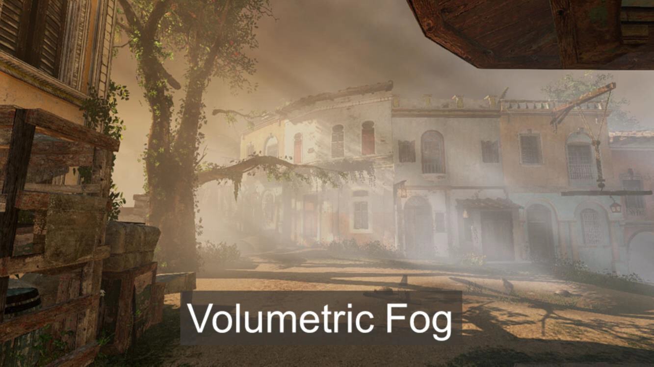
This is a try form a book:

void VolumetricFog::Load() {
pShaderProgram->CompileShader(VERTEX_SHADER, GLSLShader::VERTEX);
pShaderProgram->CompileShader(FRAGMENT_SHADER, GLSLShader::FRAGMENT);
pShaderProgram->Link();

// load noise 3D texture
int size = dim * dim * dim;
noise = new float[size];

std::random_device rd;
std::default_random_engine generator;
generator.seed(rd());
std::uniform_int_distribution<int> distribution(0, 255);

// Normalize
for (int i = 0; i < dim; i++)
	for (int j = 0; j < dim; j++)
		for (int k = 0; k < dim; k++)
			noise[IX(i, j, k)] = distribution(generator) / 255.0f;


// Pass to OpenGL
glActiveTexture(GL_TEXTURE0);
glGenTextures(1, &textureID);
glBindTexture(GL_TEXTURE_3D, textureID);

// set the texture parameters
glTexParameteri(GL_TEXTURE_3D, GL_TEXTURE_WRAP_S, GL_CLAMP_TO_EDGE);
glTexParameteri(GL_TEXTURE_3D, GL_TEXTURE_WRAP_T, GL_CLAMP_TO_EDGE);
glTexParameteri(GL_TEXTURE_3D, GL_TEXTURE_WRAP_R, GL_CLAMP_TO_EDGE);
glTexParameteri(GL_TEXTURE_3D, GL_TEXTURE_MAG_FILTER, GL_LINEAR);
glTexParameteri(GL_TEXTURE_3D, GL_TEXTURE_MIN_FILTER, GL_LINEAR_MIPMAP_LINEAR);

//set the mipmap levels (base and max)
glTexParameteri(GL_TEXTURE_3D, GL_TEXTURE_BASE_LEVEL, 0);
glTexParameteri(GL_TEXTURE_3D, GL_TEXTURE_MAX_LEVEL, 4);

glTexImage3D(GL_TEXTURE_3D, 0, GL_RED, dim, dim, dim, 0, GL_RED, GL_FLOAT, noise);

//generate mipmaps
glGenerateMipmap(GL_TEXTURE_3D);

//setup unit cube vertex array and vertex buffer objects
GLuint cubeVBOID, cubeIndicesID;
glGenVertexArrays(1, &cubeVAOID);
glGenBuffers(1, &cubeVBOID);
glGenBuffers(1, &cubeIndicesID);

//unit cube vertices 
glm::vec3 vertices[8] = { glm::vec3(-0.5f,-0.5f,-0.5f),
						glm::vec3(0.5f,-0.5f,-0.5f),
						glm::vec3(0.5f, 0.5f,-0.5f),
						glm::vec3(-0.5f, 0.5f,-0.5f),
						glm::vec3(-0.5f,-0.5f, 0.5f),
						glm::vec3(0.5f,-0.5f, 0.5f),
						glm::vec3(0.5f, 0.5f, 0.5f),
						glm::vec3(-0.5f, 0.5f, 0.5f) };

//unit cube indices
GLushort cubeIndices[36] = { 0,5,4,
						  5,0,1,
						  3,7,6,
						  3,6,2,
						  7,4,6,
						  6,4,5,
						  2,1,3,
						  3,1,0,
						  3,0,7,
						  7,0,4,
						  6,5,2,
						  2,5,1 };
glBindVertexArray(cubeVAOID);
glBindBuffer(GL_ARRAY_BUFFER, cubeVBOID);
//pass cube vertices to buffer object memory
glBufferData(GL_ARRAY_BUFFER, sizeof(vertices), &(vertices[0].x), GL_STATIC_DRAW);

//enable vertex attributre array for position
glEnableVertexAttribArray(0);
glVertexAttribPointer(0, 3, GL_FLOAT, GL_FALSE, 0, 0);

//pass indices to element array  buffer
glBindBuffer(GL_ELEMENT_ARRAY_BUFFER, cubeIndicesID);
glBufferData(GL_ELEMENT_ARRAY_BUFFER, sizeof(cubeIndices), &cubeIndices[0], GL_STATIC_DRAW);

glBindVertexArray(0);
}

void VolumetricFog::Draw()
{
Camera* pCamera = Camera::GetInstance();

projection = pCamera->GetProjection();
view = pCamera->GetViewMatrix();
model = glm::mat4(1.f);
model = glm::translate(model, mPos);

glm::mat4 MVP = projection * view * model;

glEnable(GL_BLEND);
glBindVertexArray(cubeVAOID);
//bind the raycasting shader
pShaderProgram->Use();
//pass shader uniforms
pShaderProgram->SetUniform("volume", 0);
glActiveTexture(GL_TEXTURE0);
glBindTexture(GL_TEXTURE_3D, textureID);
pShaderProgram->SetUniform("MVP", MVP);
pShaderProgram->SetUniform("camPos", pCamera->Position);
pShaderProgram->SetUniform("step_size", 1.f / dim, 1.f / dim, 1.f / dim);
//render the cube
glDrawElements(GL_TRIANGLES, 36, GL_UNSIGNED_SHORT, 0);
//unbind the raycasting shader
//disable blending
glDisable(GL_BLEND);
}

int VolumetricFog::IX(int i, int j, int k)
{
    return i + dim * j + dim * dim * k;
}

The code is pretty straight forward. First it creates noise 3D data stored in noise array and adds this data in a 3D texture. Then it generates a VAO of a cube. and then in the draw method it draws this cube.

vertex shader :

  #version 330 core

layout(location = 0) in vec3 vVertex; //object space vertex position

//uniform
uniform mat4 MVP;   //combined modelview projection matrix

smooth out vec3 vUV; //3D texture coordinates for texture lookup in the fragment shader

void main()
{  
//get the clipspace position 
gl_Position = MVP*vec4(vVertex.xyz, 1.f);

//get the 3D texture coordinates by adding (0.5,0.5,0.5) to the object space 
//vertex position. Since the unit cube is at origin (min: (-0.5,-0.5,-0.5) and max: (0.5,0.5,0.5))
//adding (0.5,0.5,0.5) to the unit cube object space position gives us values from (0,0,0) to 
//(1,1,1)
vUV = vVertex + vec3(0.5);
}

fragment shader:

#version 330 core

layout(location = 0) out vec4 vFragColor;	//fragment shader output

smooth in vec3 vUV;				//3D texture coordinates form vertex shader 
							//interpolated by rasterizer

//uniforms
uniform sampler3D	volume;		//volume dataset
uniform vec3		camPos;		//camera position
uniform vec3		step_size;	//ray step size 

//constants
const int MAX_SAMPLES = 300;	//total samples for each ray march step
const vec3 texMin = vec3(0);	//minimum texture access coordinate
const vec3 texMax = vec3(1);	//maximum texture access coordinate

void main()
{ 
//get the 3D texture coordinates for lookup into the volume dataset
vec3 dataPos = vUV;

//Getting the ray marching direction:
//get the object space position by subracting 0.5 from the
//3D texture coordinates. Then subtraact it from camera position
//and normalize to get the ray marching direction
vec3 geomDir = normalize((vUV-vec3(0.5)) - camPos); 

//multiply the raymarching direction with the step size to get the
//sub-step size we need to take at each raymarching step
vec3 dirStep = geomDir * step_size; 
 
//flag to indicate if the raymarch loop should terminate
bool stop = false; 

//for all samples along the ray
for (int i = 0; i < MAX_SAMPLES; i++) {
	// advance ray by dirstep
	dataPos = dataPos + dirStep;
	
	
	//The two constants texMin and texMax have a value of vec3(-1,-1,-1)
	//and vec3(1,1,1) respectively. To determine if the data value is 
	//outside the volume data, we use the sign function. The sign function 
	//return -1 if the value is less than 0, 0 if the value is equal to 0 
	//and 1 if value is greater than 0. Hence, the sign function for the 
	//calculation (sign(dataPos-texMin) and sign (texMax-dataPos)) will 
	//give us vec3(1,1,1) at the possible minimum and maximum position. 
	//When we do a dot product between two vec3(1,1,1) we get the answer 3. 
	//So to be within the dataset limits, the dot product will return a 
	//value less than 3. If it is greater than 3, we are already out of 
	//the volume dataset
	stop = dot(sign(dataPos-texMin),sign(texMax-dataPos)) < 3.0;

	//if the stopping condition is true we brek out of the ray marching loop
	if (stop) 
		break;
	
	// data fetching from the red channel of volume texture
	float sample = texture(volume, dataPos).r;	
	
	//Opacity calculation using compositing:
	//here we use front to back compositing scheme whereby the current sample
	//value is multiplied to the currently accumulated alpha and then this product
	//is subtracted from the sample value to get the alpha from the previous steps.
	//Next, this alpha is multiplied with the current sample colour and accumulated
	//to the composited colour. The alpha value from the previous steps is then 
	//accumulated to the composited colour alpha.
	float prev_alpha = sample - (sample * vFragColor.a);
	vFragColor.rgb = prev_alpha * vec3(sample) + vFragColor.rgb; 
	vFragColor.a += prev_alpha; 
		
	//early ray termination
	//if the currently composited colour alpha is already fully saturated
	//we terminated the loop
	if( vFragColor.a>0.99)
		break;
} 
}

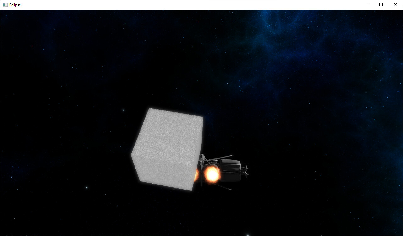
this cube on the picture is the result :


as expected there is a cube with noise as texture. I can not understand how the book (“OpenGL Development Cookbook”) expected to draw a volume with this setup. Am I missing something?