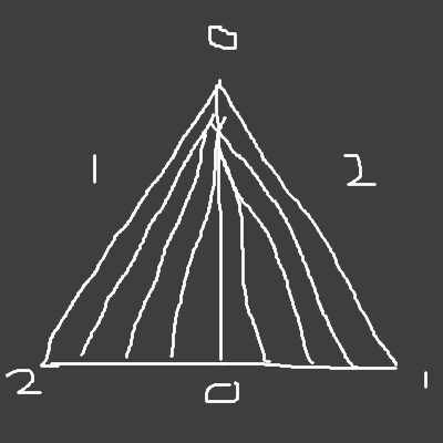
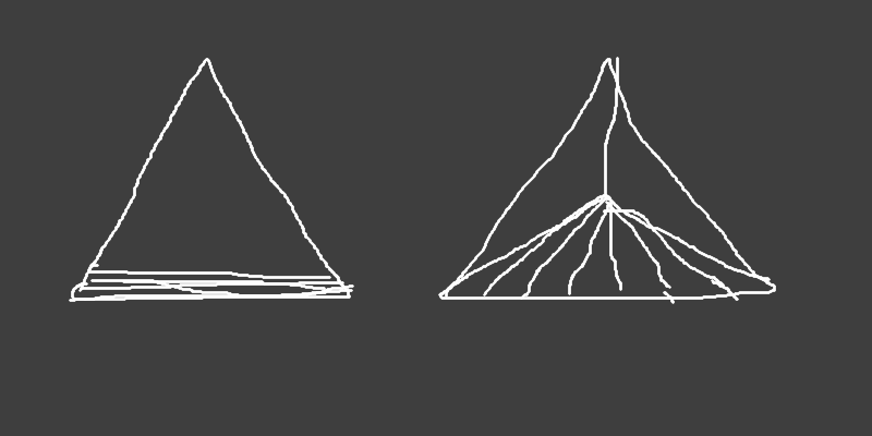
The image on the left is what I get. All the lines on the bottom are exactly overlapping the bottom edge, but they are different colors so I can see them flickering. The image on the right is what I was expecting.
That’s not a “standard formula”. That’s what you use when you don’t want tessellation to affect the geometry of the object in question.
Also:
… how exactly are you doing that? Is there some flat-qualified output from the TES? If so, what are you doing to ensure that the right output vertex (the one that controls the flat value) is getting the right color?
It’s really difficult to debug a problem without actual source code. This back-and-forth where I ask about a tiny bit of code and you reply with just that tiny bit of code is just not a very productive way to handle this.
What other difference could there be? That’s what tessellation is: it takes an abstract primitive patch and breaks it up into smaller primitives. The only difference in the vertices generated is where they are within the space of the abstract patch.
If the way the tessellation breaks up the surface is consistent, then it would be useful to know which vertex is which. I had to add a one extra inner layer to the triangle in order to produce tessellation coordinates that could be interpreted.
What does that mean? Other than their position within the abstract patch, what other difference is there? It’s the abstract patch that gets tessellated, and the only parameter it has is its position.
What do you mean by “one extra inner layer”? What value did you originally pass, and what coordinates did you get using that value?
I mean gl_TessLevelInner. I think I was setting it to 1.0 in the first example above, and I wasn’t able to create a triangle fan until I set it to 2.0.
If the outer tess level is 10, it’s going to produce ten vertices on that edge. It would be useful to know that the vertex is in the outer tess level, and which one it is. Otherwise, all you can do is estimate by dividing the floating point value and praying your tolerance comparison value isn’t too high.
Anyways, I got this all worked out for all possible combinations of edge tessellations, for triangles and quads. I don’t claim to understand the entire thing completely, but if you can tessellate on one axis instead of two the number of times the evaluation shader has to run is decreased to the square root.
No, it will produce eleven on that edge. The tessellation level is how many segments are produced for that edge. The number of vertices is one greater than the number of segments.
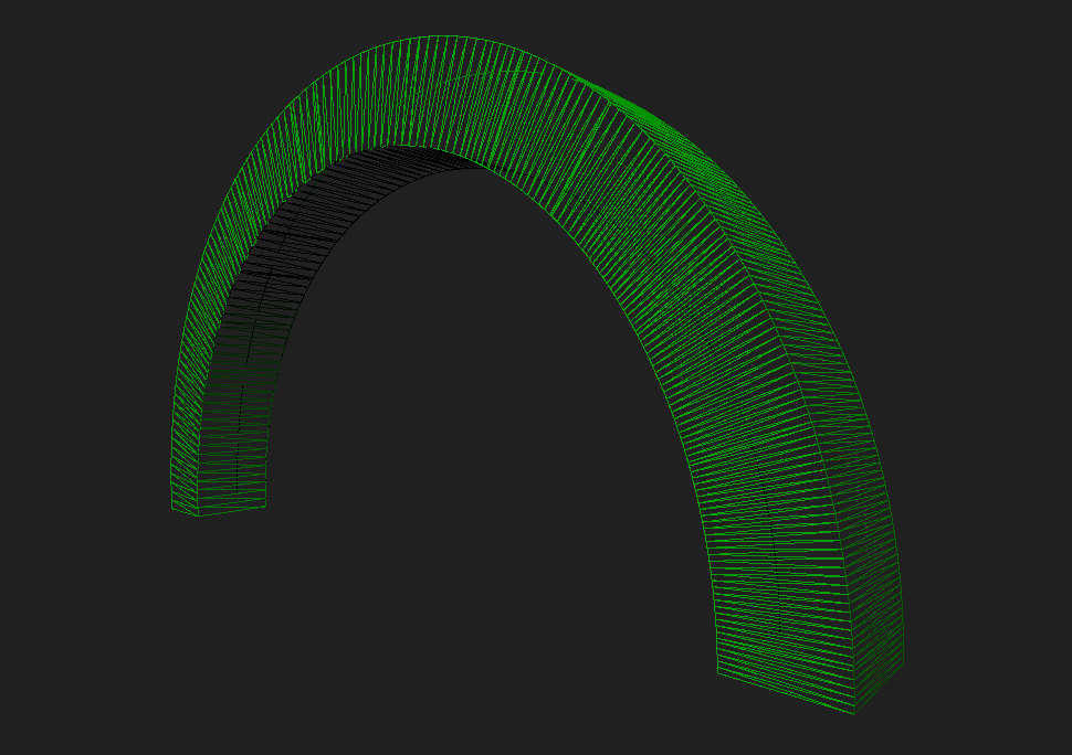
I think my problem is solved, at least for now. This animation shows what the original mesh geometry looks like, although this version is less optimal than my image above: