Calculating tight ortho projection matrix for shadow mapping

I’m trying to calculate tight ortho projection around the camera for better shadow mapping. I’m first calculating the camera frustum 8 points in world space using basic trigonometry using fov, position, right, forward, near, and far parameters of the camera as follows:

PerspectiveFrustum::PerspectiveFrustum(const Camera* camera)
{
	float nearHalfHeight = tanf(camera->GetFov() / 2.0f) * camera->GetNear();
	float nearHalfWidth = nearHalfHeight * Screen::GetWidth() / Screen::GetHeight();
	float farHalfHeight = tanf(camera->GetFov() / 2.0f) * camera->GetFar();
	float farHalfWidth = farHalfHeight * Screen::GetWidth() / Screen::GetHeight();

	glm::vec3 nearCenter = camera->GetEye() + camera->GetForward() * camera->GetNear();
	glm::vec3 nearTop = camera->GetUp() * nearHalfHeight;
	glm::vec3 nearRight = camera->GetRight() * nearHalfWidth;

	glm::vec3 farCenter = camera->GetEye() + camera->GetForward() * camera->GetFar();
	glm::vec3 farTop = camera->GetUp() * farHalfHeight;
	glm::vec3 farRight = camera->GetRight() * farHalfWidth;

	m_RightNearBottom = nearCenter + nearRight - nearTop;
	m_RightNearTop = nearCenter + nearRight + nearTop;
	m_LeftNearBottom = nearCenter - nearRight - nearTop;
	m_LeftNearTop = nearCenter - nearRight + nearTop;
	m_RightFarBottom = farCenter + farRight - farTop;
	m_RightFarTop = farCenter + farRight + farTop;
	m_LeftFarBottom = farCenter - farRight - farTop;
	m_LeftFarTop = farCenter - farRight + farTop;
}

Then I calculate the frustum in light view and calculating the min and max point in each axis to calculate the bounding box of the ortho projection as follows:

inline glm::mat4 GetView() const
{
    return glm::lookAt(m_Position, glm::vec3(0.0f, 0.0f, 0.0f), glm::vec3(0.0f, 1.0f, 0.0f));
}
 
glm::mat4 DirectionalLight::GetProjection(const Camera& camera) const
{
    PerspectiveFrustum frustum = camera.GetFrustum();
    glm::mat4 lightView = GetView();
    std::array<glm::vec3, 8> frustumToLightView
    {
        lightView * glm::vec4(frustum.m_RightNearBottom, 1.0f),
        lightView * glm::vec4(frustum.m_RightNearTop, 1.0f),
        lightView * glm::vec4(frustum.m_LeftNearBottom, 1.0f),
        lightView * glm::vec4(frustum.m_LeftNearTop, 1.0f),
        lightView * glm::vec4(frustum.m_RightFarBottom, 1.0f),
        lightView * glm::vec4(frustum.m_RightFarTop, 1.0f),
        lightView * glm::vec4(frustum.m_LeftFarBottom, 1.0f),
        lightView * glm::vec4(frustum.m_LeftFarTop, 1.0f)
    };
 
    glm::vec3 min{ INFINITY, INFINITY, INFINITY };
    glm::vec3 max{ -INFINITY, -INFINITY, -INFINITY };
    for (unsigned int i = 0; i < frustumToLightView.size(); i++)
    {
        if (frustumToLightView[i].x < min.x)
            min.x = frustumToLightView[i].x;
        if (frustumToLightView[i].y < min.y)
            min.y = frustumToLightView[i].y;
        if (frustumToLightView[i].z < min.z)
            min.z = frustumToLightView[i].z;
 
        if (frustumToLightView[i].x > max.x)
            max.x = frustumToLightView[i].x;
        if (frustumToLightView[i].y > max.y)
            max.y = frustumToLightView[i].y;
        if (frustumToLightView[i].z > max.z)
            max.z = frustumToLightView[i].z;
    }
    return glm::ortho(min.x, max.x, min.y, max.y, min.z, max.z);
}

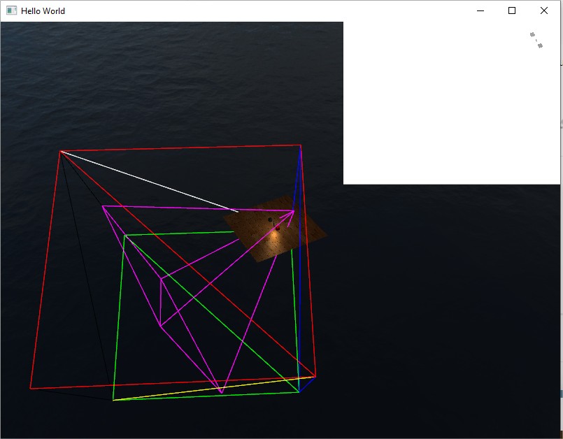
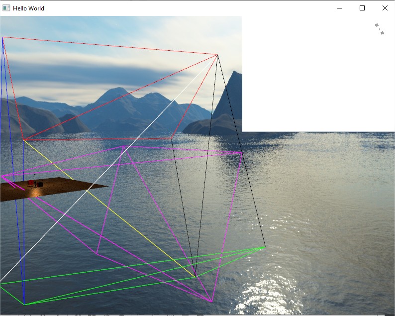
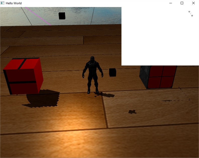
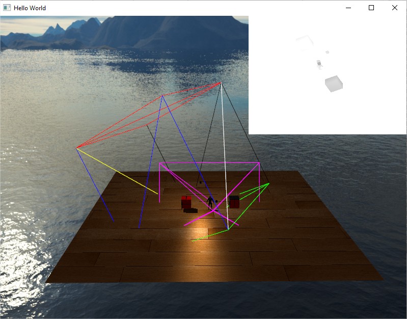
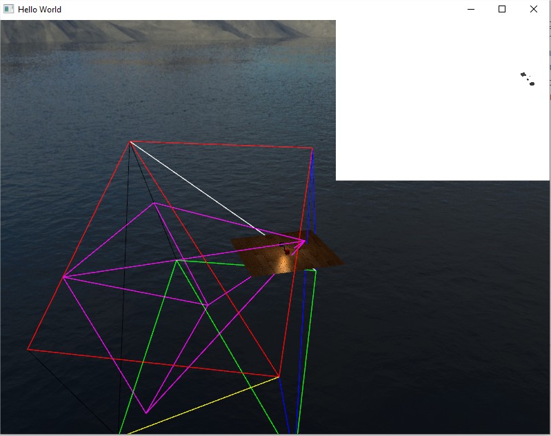
Here’s captured results as you can see top left corner quad shows the shadow map which is completely wrong result as can be seen:

(The smearing of the shadow map values is just an artifact of the gif compresser I used it doesn’t really happen so there’s no problem of me not clearing the z-buffer of the FBO)

Nothing stands out in the posted code.

Use a debugger to view the values of the variables involved. Do the numbers look right? Also, try rendering the cube generated by PerspectiveFrustum but with {near,Far}half{Width,Height} scaled by 0.99; the result should be just inside the edge of the window.

GetFov() returns the angle in radians, right?

FWIW, the way that I’d implement PerspectiveFrustum is to get the camera matrix (world space to clip space transformation = projection * view), invert it, transform the 8 corners of the signed unit cube (i.e. [x,y,z,1] for x,y,z∈{-1,1}), then divide each by W.

Other than that, check that all of the transformations used to calculate the projection are the ones which are actually being used for rendering.

Ok few things GetFov() indeed returned degrees and not radians… changes it.
I Also try the transformation from NDC to world space with the following code:

	glm::mat4 inverseProjectViewMatrix = glm::inverse(camera.GetProjection() * camera.GetView());

	std::array<glm::vec4, 8> NDC =
	{
		glm::vec4{-1.0f, -1.0f, 0.0f, 1.0f},
		glm::vec4{1.0f, -1.0f, 0.0f, 1.0f},
		glm::vec4{-1.0f, 1.0f, 0.0f, 1.0f},
		glm::vec4{1.0f, 1.0f, 0.0f, 1.0f},
		glm::vec4{-1.0f, -1.0f, 1.0f, 1.0f},
		glm::vec4{1.0f, -1.0f, 1.0f, 1.0f},
		glm::vec4{-1.0f, 1.0f, 1.0f, 1.0f},
		glm::vec4{1.0f, 1.0f, 1.0f, 1.0f},
	};

	for (size_t i = 0; i < NDC.size(); i++)
	{
		NDC[i] = inverseProjectViewMatrix * NDC[i];
		NDC[i] /= NDC[i].w;
	}

For the far coordinates of the frustum they’re equal to my calculation of the frustum, but for the near corners they’re off as if my calculation of the near corners is halved by 2 (for x and y only).
For example:
RIGHT TOP NEAR CORNER:
my calculation yields - {0.055, 0.041, 2.9}
inverse NDC yields - {0.11, 0.082, 2.8}

So I’m not sure where my calculation got wrong, maybe you could point out?
Even with the inversed NDC coordinates I tried to use them as following:

glm::mat4 DirectionalLight::GetProjection(const Camera& camera) const
{
	glm::mat4 lightView = GetView();

	glm::mat4 inverseProjectViewMatrix = glm::inverse(camera.GetProjection() * camera.GetView());

	std::array<glm::vec4, 8> NDC =
	{
		glm::vec4{-1.0f, -1.0f, 0.0f, 1.0f},
		glm::vec4{1.0f, -1.0f, 0.0f, 1.0f},
		glm::vec4{-1.0f, 1.0f, 0.0f, 1.0f},
		glm::vec4{1.0f, 1.0f, 0.0f, 1.0f},
		glm::vec4{-1.0f, -1.0f, 1.0f, 1.0f},
		glm::vec4{1.0f, -1.0f, 1.0f, 1.0f},
		glm::vec4{-1.0f, 1.0f, 1.0f, 1.0f},
		glm::vec4{1.0f, 1.0f, 1.0f, 1.0f},
	};

	for (size_t i = 0; i < NDC.size(); i++)
	{
		NDC[i] = lightView * inverseProjectViewMatrix * NDC[i];
		NDC[i] /= NDC[i].w;
	}

	glm::vec3 min{ INFINITY, INFINITY, INFINITY };
	glm::vec3 max{ -INFINITY, -INFINITY, -INFINITY };
	for (unsigned int i = 0; i < NDC.size(); i++)
	{
		if (NDC[i].x < min.x)
			min.x = NDC[i].x;
		if (NDC[i].y < min.y)
			min.y = NDC[i].y;
		if (NDC[i].z < min.z)
			min.z = NDC[i].z;

		if (NDC[i].x > max.x)
			max.x = NDC[i].x;
		if (NDC[i].y > max.y)
			max.y = NDC[i].y;
		if (NDC[i].z > max.z)
			max.z = NDC[i].z;
	}
	return glm::ortho(min.x, max.x, min.y, max.y, min.z, max.z);
}

And still got bad result:

That’s because your Z values are 0 and 1 when they should be -1 and 1.

Hmm right my bad.
Ok no both calculation are the same. So I’m not really sure why this still doesn’t work any ideas? (Almost same result as the second gif)

Because of the near plane.

If you set the light’s frustum to tightly bound the view frustum, the shadow map won’t contain objects which are outside the view frustum. But it needs to include objects whose shadow intersects the view frustum even when the object itself doesn’t.

IOW, using the view frustum’s bounding box as the light frustum is fine for five of the planes, but the near plane needs to be close enough to the light to also include objects between the light and the nearest point of the view frustum.

Even by adding negative margin to the near plane with the following code change:

return glm::ortho(min.x, max.x, min.y, max.y, min.z - 50.0f, max.z);

Gets me this result:

Any suggestions, I’m pretty much lost at this point.

When you render the shadow map, render to a colour buffer as well as a depth buffer and display the result.

OKAY!
I get a feeling I understand what’s going on with a few tests I did.
I decided to draw wireframe of the light frustum as-well as the camera view of a camera that is statically located at:
(0.0, 5.0, 15.0) with near plane at 0.1 and far plane at 100.0
This is the view of the scene from this point:


I also hardcoded the values of the light projection just so I could show you what shadows should be visible from this POV of the camera.
Now the following picture is the static camera frustum (in magenta) and the light frustum (rainbow - each face different color):

As can be seen the light frustum envelop the view frustum except for the near (red) and far (green) place where there’s slight offset:

The view frustum going through the light frustum’s far plane, and the light frustum’s near plane have some extra space between it and the top of the view frustum.
This light frustum was generated with the following ortho projection calculation:
return glm::ortho(min.x, max.x, min.y, max.y, min.z, max.z);
So I did not add offset in this example which seems weird since this code should produce a light frustum that exactly envelop the view frustum isn’t it? So I’m not sure what wrong here… but! even with that little error as can be seen the light frustum is still enveloping all the necessary areas that needs to be shadow for this static camera position, so why the shadows still looks wrong as can be seen?:

Well… I’ve looked at the shadow map (right top corner) in this screen and it seems to me that what causing it is the precision of the shadow map generated not because of the shadow map resolution but because of how big is light frustum making the scene almost to not exist in the shadow map.
And what’s causing it? Well seems from the writeframes that the far plane of the view frustum is the culprit. So I’ve tested the same scene with the static camera positioned the same but with far plane of 20.0 instead of 100.0:

So what does it achieved? Well the shadow are much more crispier then before because the light frustum is much small and the scene is written to much larger area of the shadow map given the sampler better precision when choosing shadow values… but still the right most cube is missing its shadow because of the light frustum not enveloping the whole view frustum which I’m still not sure why.

So concluding from all of these I have 2 problems here:

  1. Why the calculation of the bounding box of the light frustum not enveloping the view frustum exactly? (This is causing missing shadows)
  2. What can I do when the clipping space of the view is somewhat large due to high range between near and far planes of the camera which is causing the light frustum to grow in size and capture the scene depth into the shadow map from much larger distance causing bad shadow resolution? I think the initial range of the static camera (100.0) is not so big value if I go less than that I wouldn’t be able to see much in the distance for bigger scenes… so what can be done since it doesn’t seems the problem of the technique but more of a resolution to how big is the view frustum (or no so that big?)

Ok realized one of my mistakes is here:
return glm::ortho(min.x, max.x, min.y, max.y, min.z, max.z);
Needs to be:
return glm::ortho(min.x, max.x, min.y, max.y, -max.z, -min.z);
because max.z is positive and in NDC the positive z axis is towards us so need to set it as the near plane flipped same for min.z.
Now I’m still remaining with the problem that the light frustum covering the whole view frustum is too big resulting in missing shadow due to low resolution of shadow map when writing z values of the scene from far away and a new problem I noticed is that that extra margin that needs to be added for when shadows are coming behind the view frustum is not always on the near side of the light frustum… for example here:


We need to add extra margin behind the view frustum to to blue face of the light frustum which is the right side of the light frustum not the near side. So how can I know which side needs to be padded with extra margin?

The one toward the light.

You define your light’s view frustum for rendering from the light’s perspective in the light’s eye-space (where light rays point down the -Z axis). In this space, define the light frustum’s left/right/bottom/top/far planes to encompass the bounds of the camera’s view frustum (**1). For the light near plane however, you in theory have to back this all the way back up to the light source (the sun or moon). In practice though, you only have to back this up to encompass the object closest to the light source that may cast shadows into your frustum, which is “significantly” less far (**2). This is your light-space view frustum.

You can use this to setup your viewing and ortho projection transforms when rendering the shadow map from the light’s perspective. You can also use this for light-space frustum clipping too (**3).

**1 There are many variations on this. In general, the method described above is conservative about including all possible casters that may cast into the frustum. You can further limit this though by using the bounds of the casters and receivers (in your light’s eye-space, of course). But you want to be cautious using either method if you care about shadow stability. To avoid “shadow edge crawling” as your scene animates, consider fitting your frustum to the bounding sphere surrounding your view frustum (or frustum partition). With this, you can eliminate large changes in shadow resolution with changes in the angle between the camera and the light source. And by quantizing your light-space origins to shadow texel centers, you can eliminate all shadow edge crawling for shadows cast from stationary objects as the camera moves. Let me know if you want a reference or two.

**2 For the case where the light source is away from the horizon, you’ll find that you often don’t have to go back very far. There usually aren’t many large, shadow-casting airborne objects that are that far off the ground. The worst case of course being when the light source is near the horizon, in which case you really have to put a cap on how far back toward the light source you go or you’ll pull in too much shadow-casting content. Some LOD may be needed here for good performance.

**3 It’s worth nothing that you can sometimes get even tighter culling results by culling to an 11-sided frustum instead of a 6-sided frustum. It’s just a few extra dot products per bsphere cull. While less important when rendering a single shadow map for the entire camera view frustum, this can yield big benefits when rendering shadow maps for camera view sub-frustums (aka splits or partitions), ala Cascaded Shadow Maps (aka Parallel-Split Shadow Maps). Again, just let me know if you want some references.

Is the magenta showing the actual view frustum, or just the far plane and the viewpoint?

I see thanks!
I’m not worrying about this “shadow edge crawling” yet since I didn’t implement animation, so one thing at a time for me I guess.
As for my second problem if I understand you correctly, the shadow map is covering too large area to get actual detail, and in my example since the sun is not in the horizon you suggest I can mitigate this problem by making the near and far planes of the light’s frustum closer? (Unless the sun is in the horizion - infront of the camera’s view frustum?)

Also would CSM help with this problem too?
Would love to get resources on this if so

Yes the magenta is the world space view frustum (in that case the static camera I’ve placed to debug all this)

No. This was to address your “missing shadows” problem.

I (and GClements) were just describing how to compute the bounds of your light space frustum so that it includes all required shadow casting objects, and this so that you don’t get “missing shadows”. Failing to compute (or apply) this light space frustum correctly is probably the most likely cause of “missing shadows”. (You could also have missing shadows because the shadow of an object is smaller than 1 shadow map texel, but that’s less likely given a properly computed light-space frustum and reasonable shadow texture size.)

Separate from this is the spatial shadow map resolution. The resolution in XY is going to be driven by how you compute those left/right/bottom/top planes for the light-space frustum. And the resolution in Z (depth) is going to be driven by how you compute the near/far planes for the light-space frustum.

CSM helps improve your spatial shadow map resolution. It still requires that you can properly compute a light space shadow map frustum including all necessary casters, so it doesn’t address your missing shadows.

In ShaderX6, Michael Valient’s chapter “Stable Rendering of Cascaded Shadow Maps” is a worthwhile read.